Prototype 1

P1 — Feasibility
Feasibility Prototype
Can it work at all?
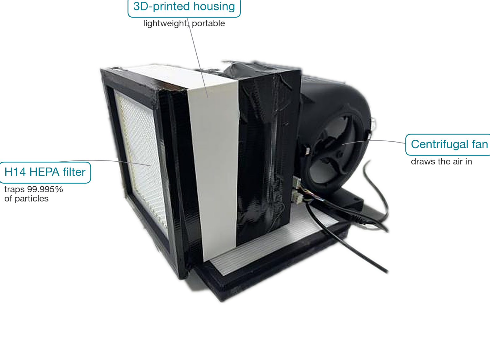
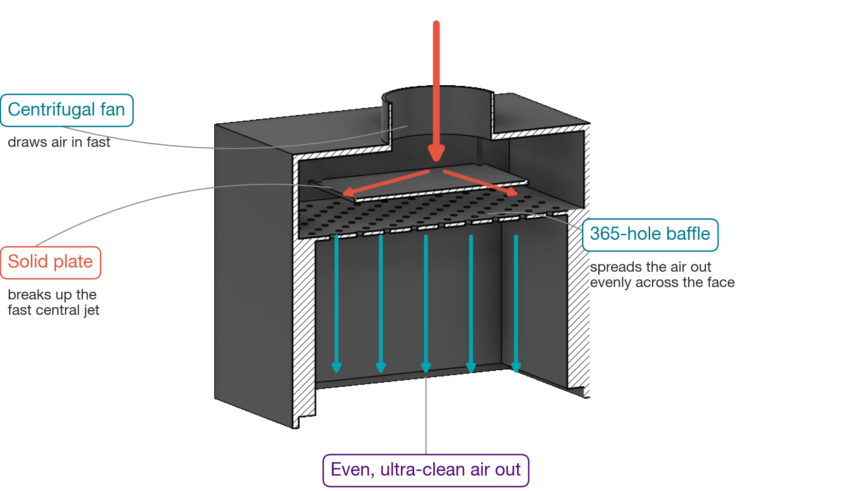
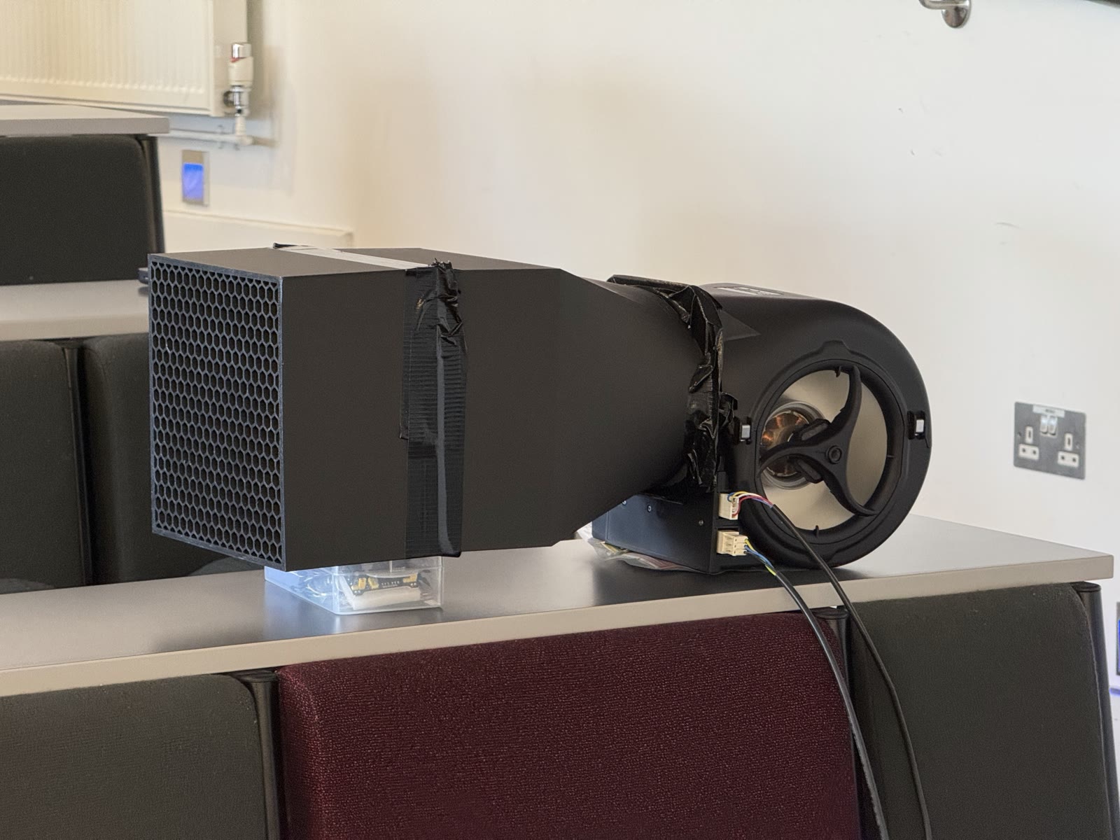
Built to answer one question: can a portable, fan-driven, HEPA-filtered canopy produce measurable airflow?
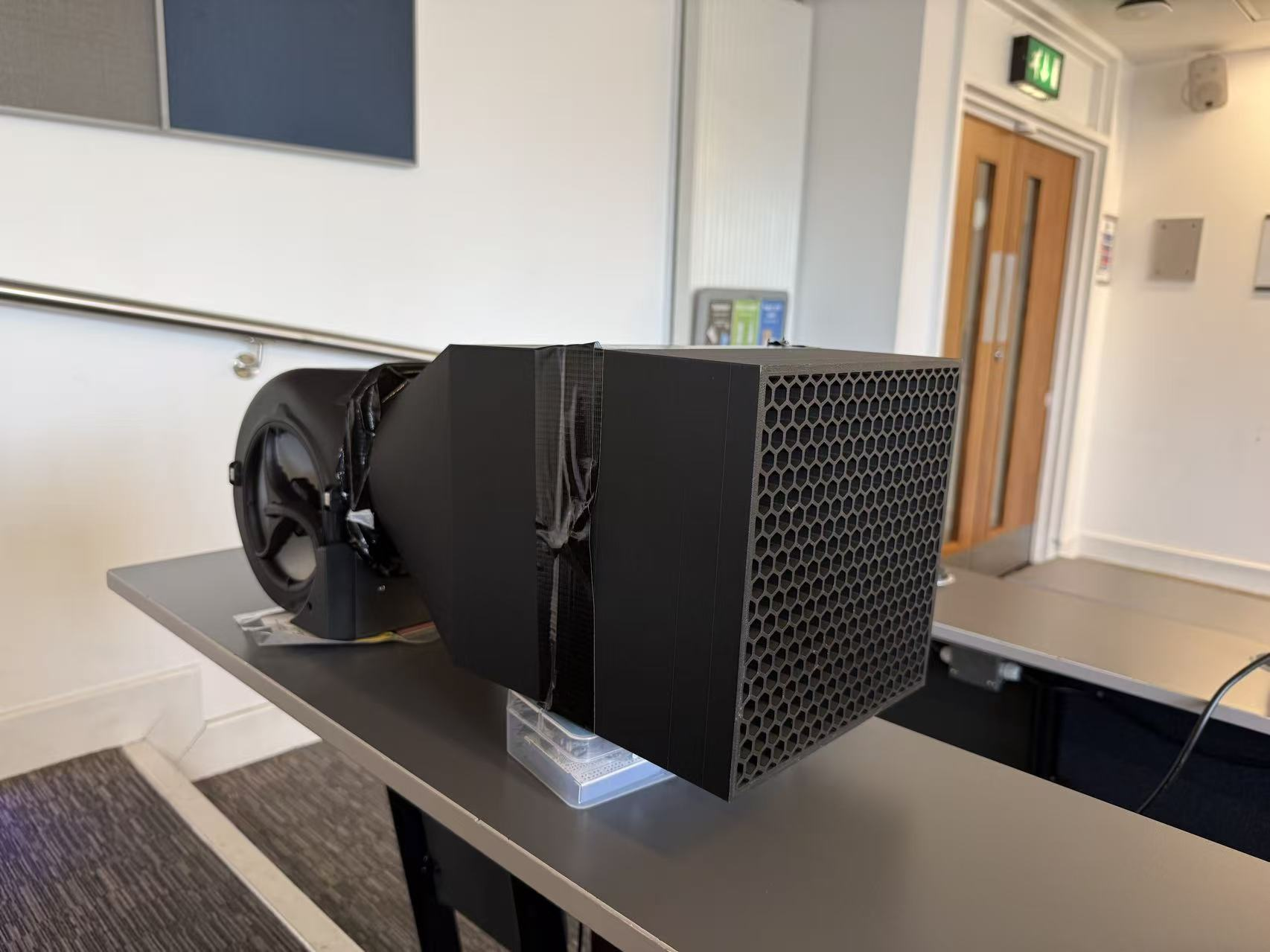
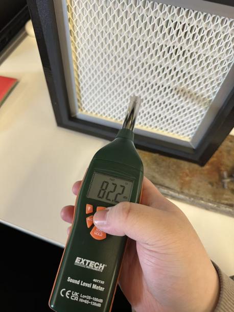
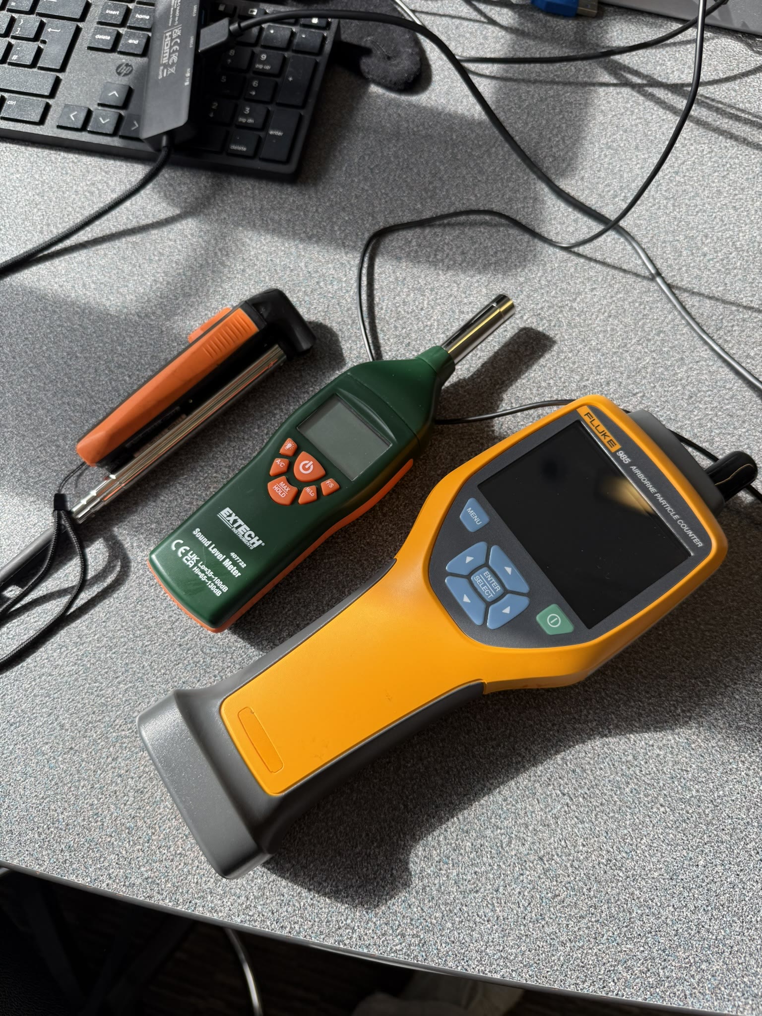
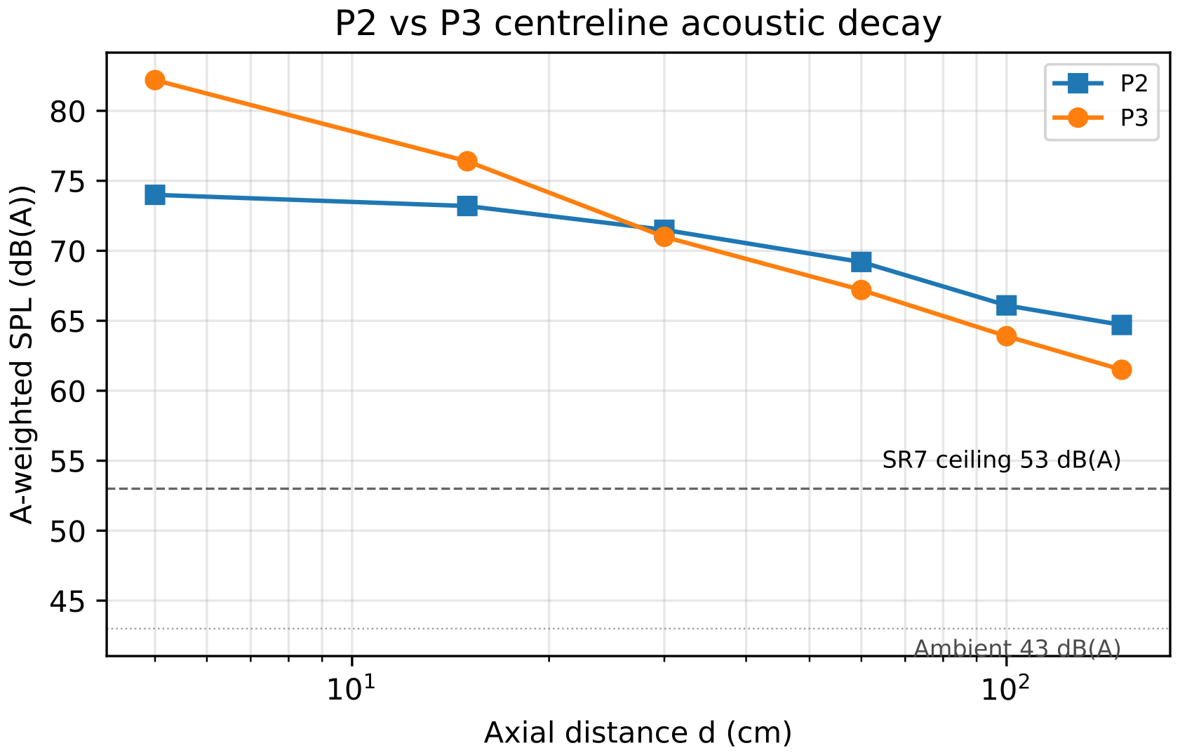
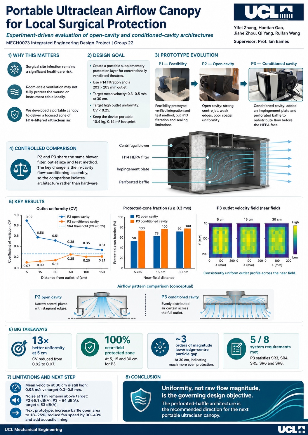
P1 used a 5-inch mixed-flow hobby fan and an H13 filter — failing the H14 specification requirement (SR3). Noise at 60 dB(A) exceeded the SR7 ceiling. The concept was validated, but critical hardware limitations were identified.
H13
Filter grade (below H14 target)
60 dB(A)
Noise (above 53 dB(A) target)
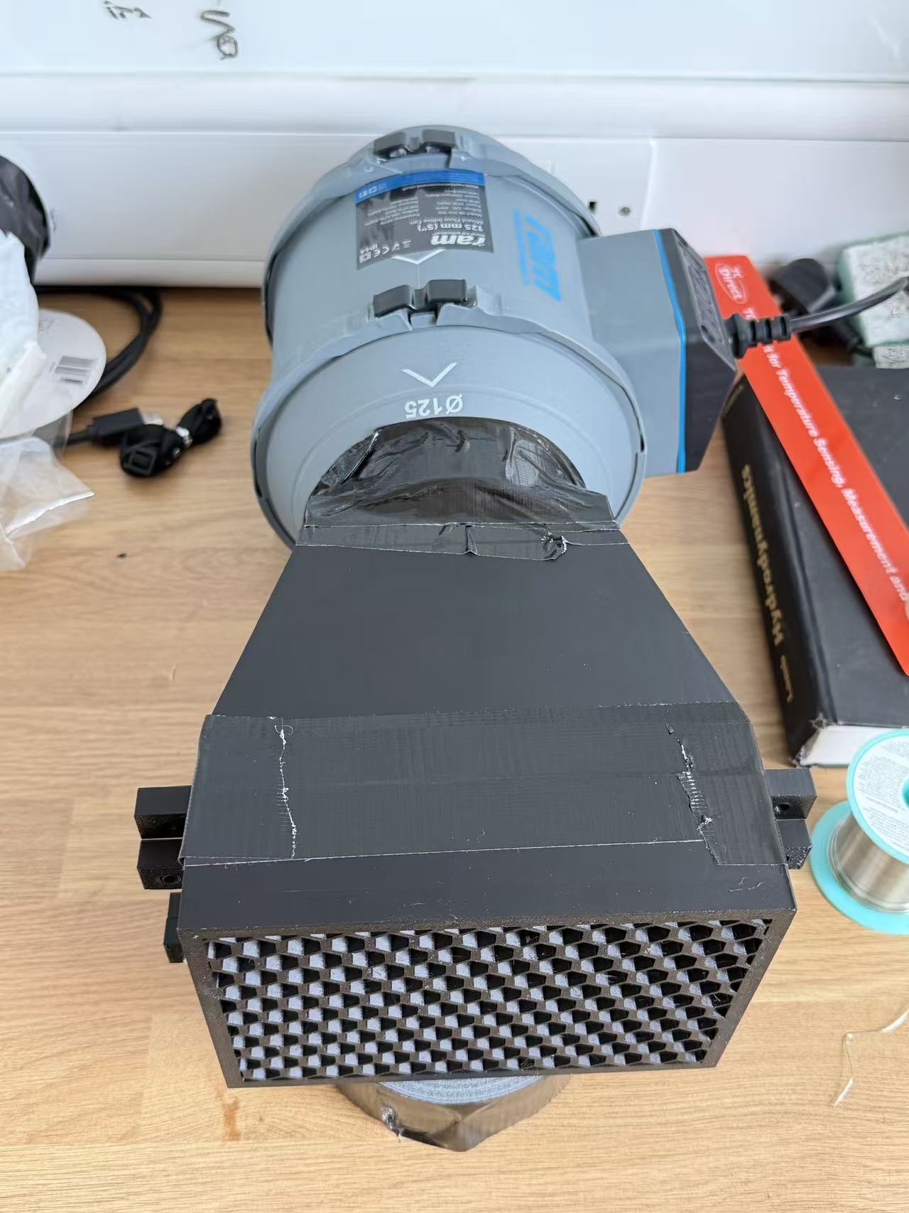
PLA
Housing material (taped)
Proved concept
Outcome
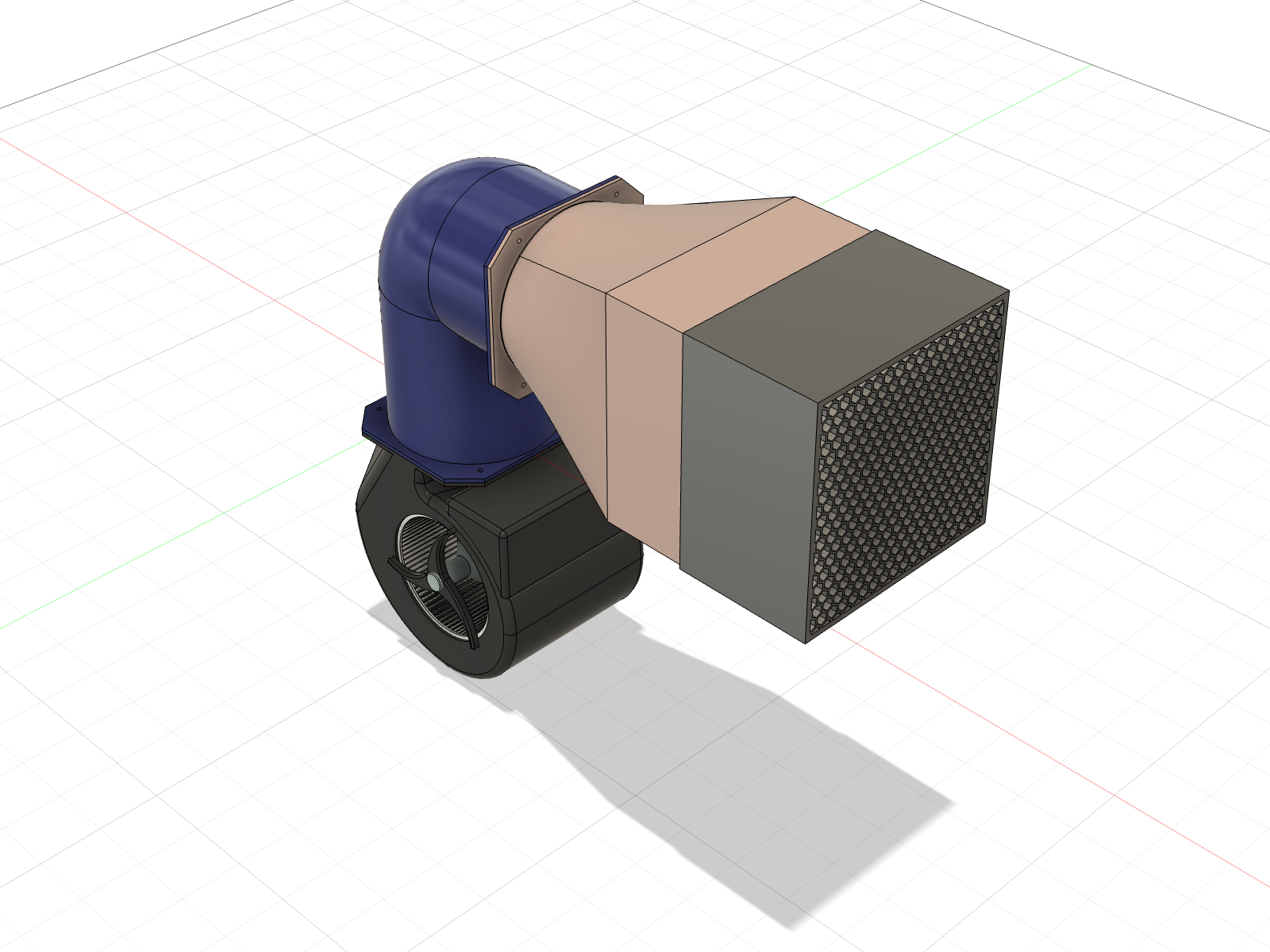
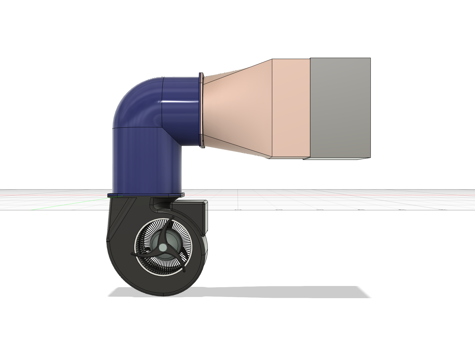
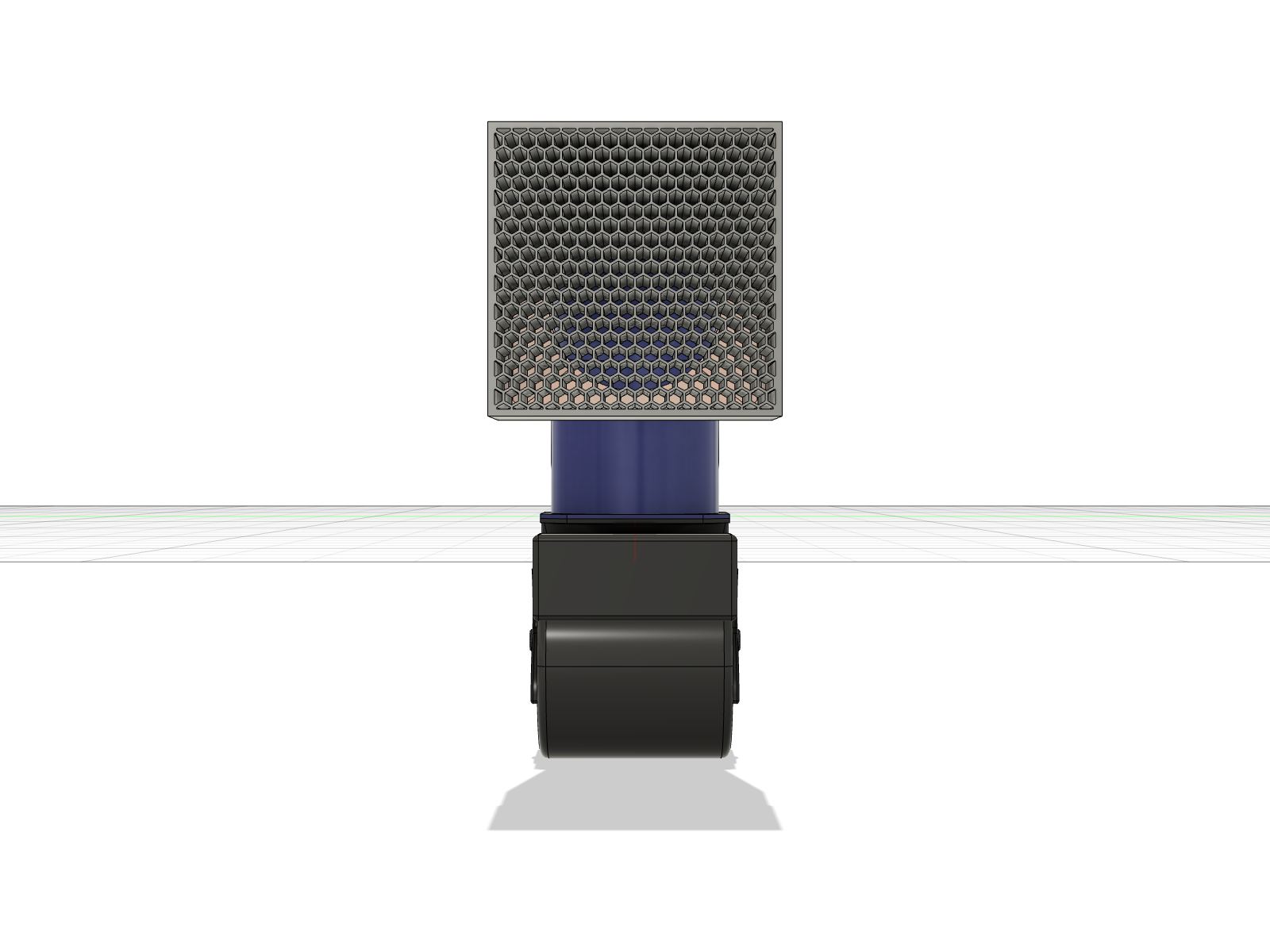
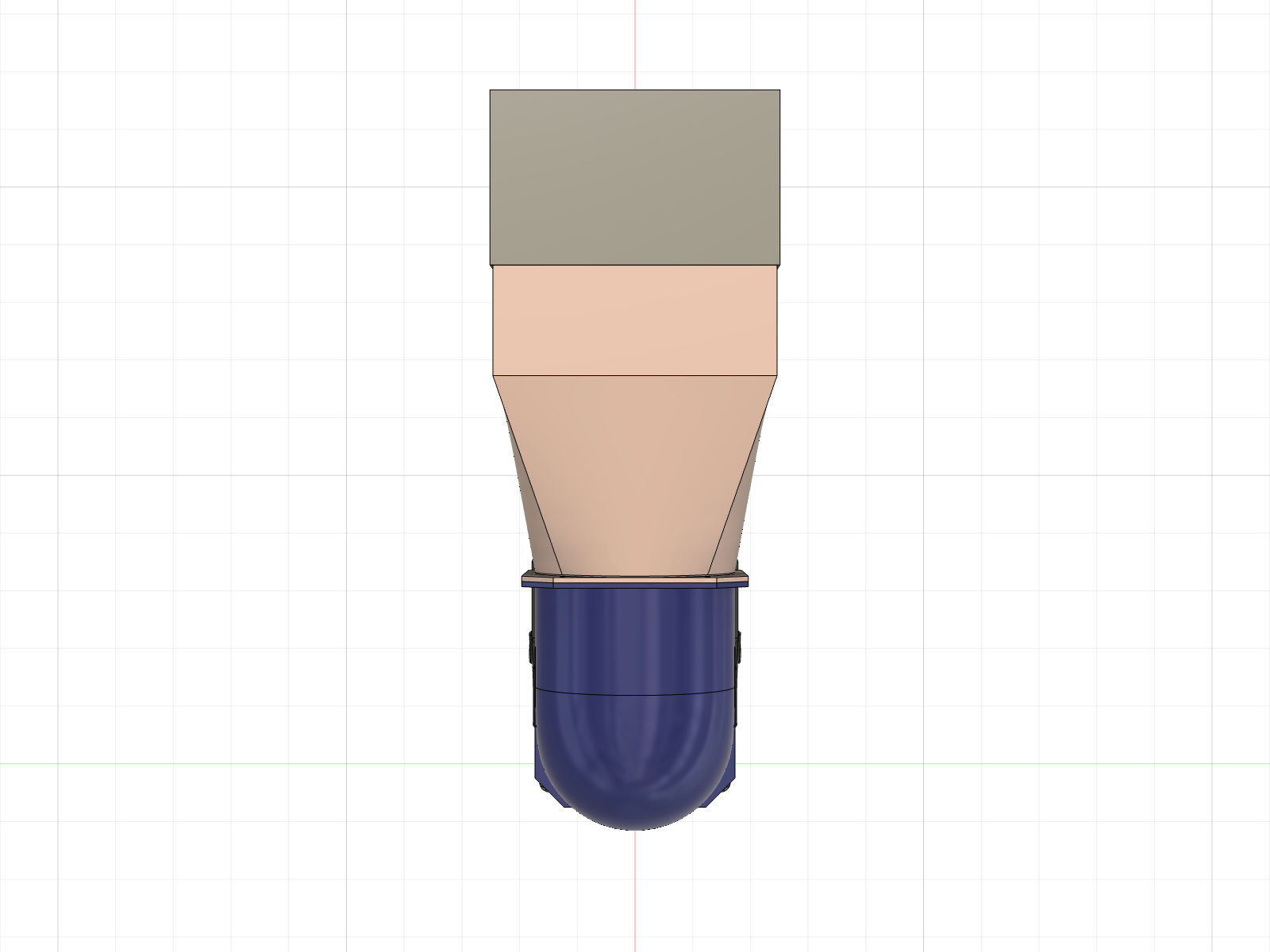
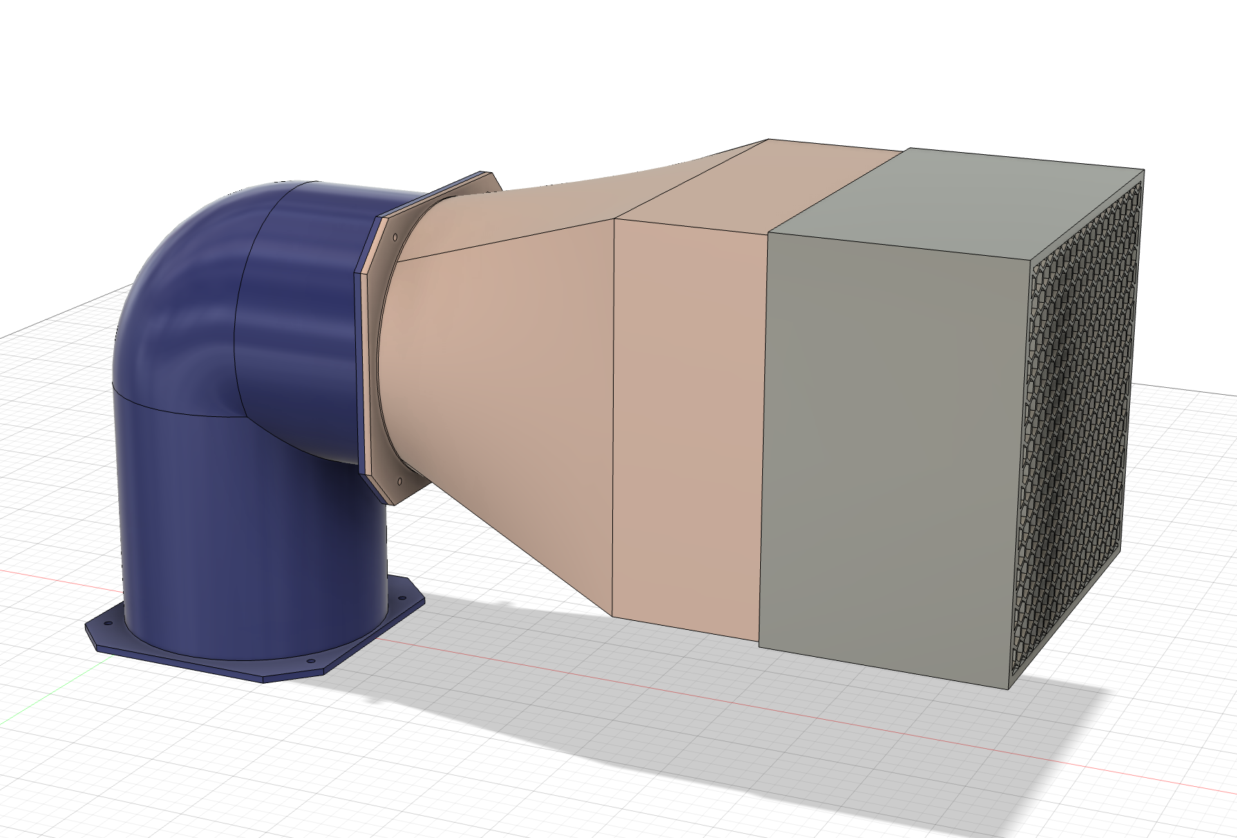
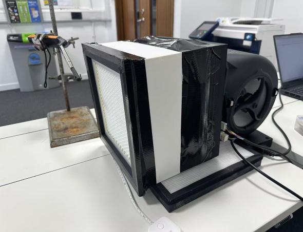
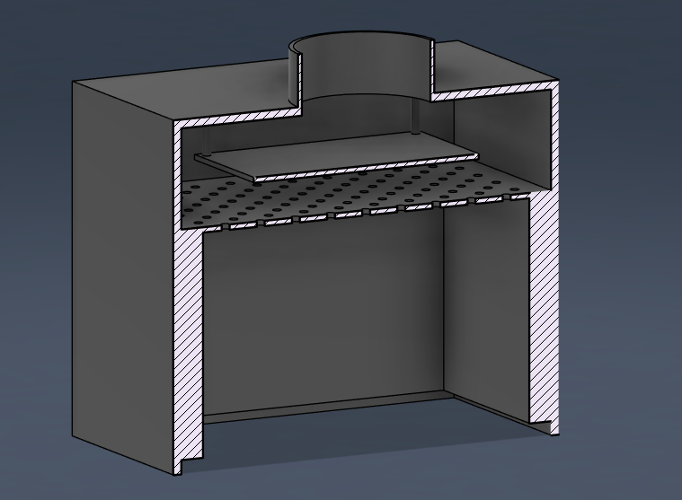
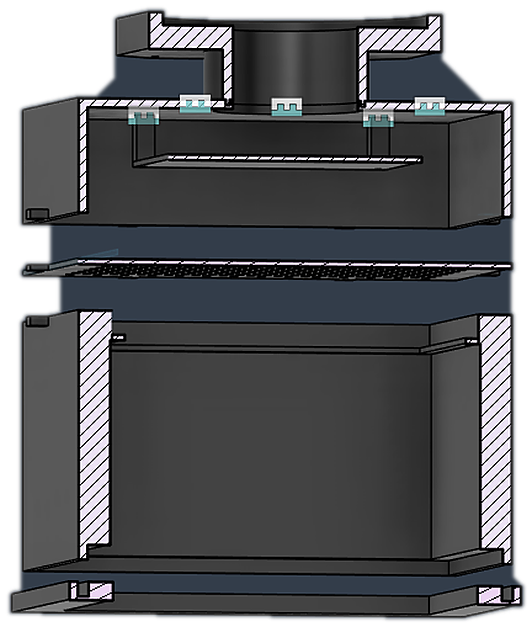
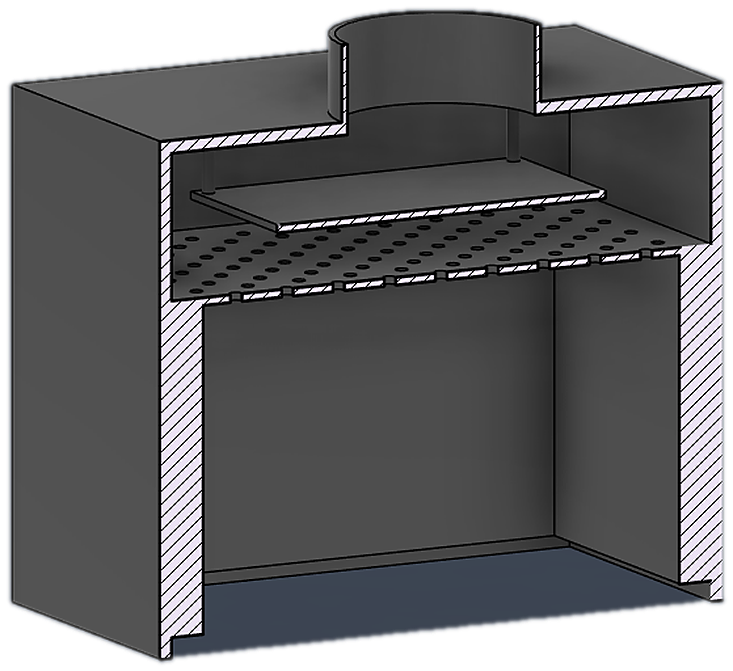
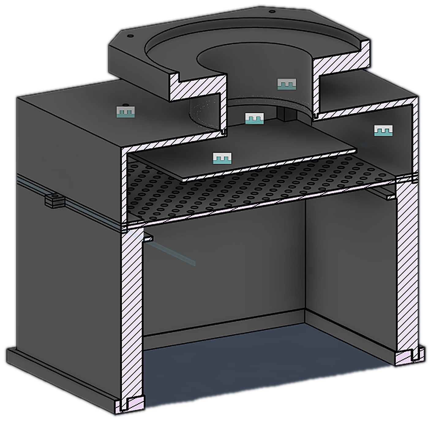
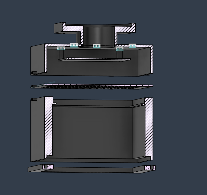
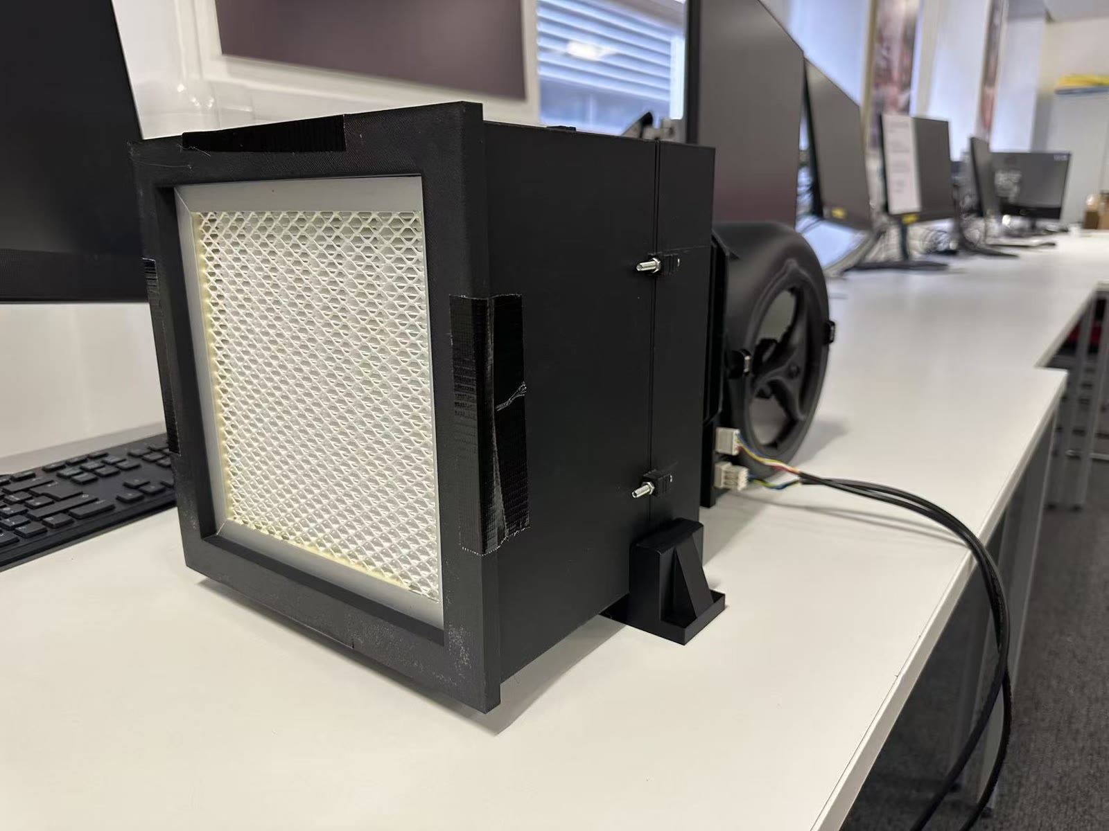
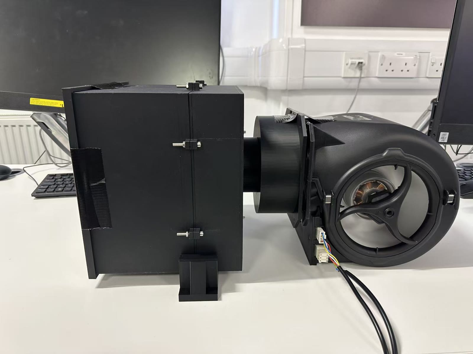
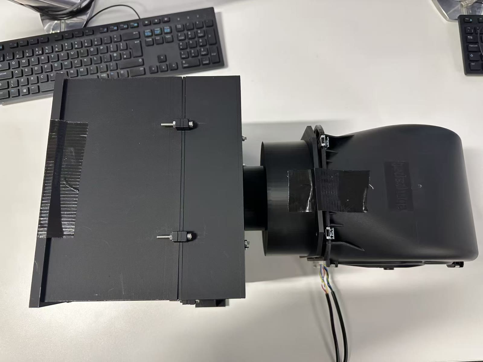
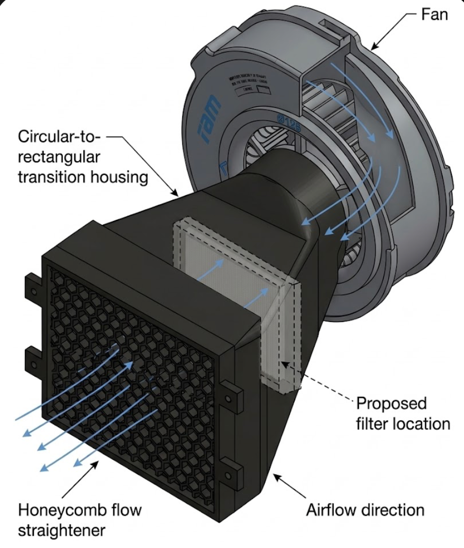
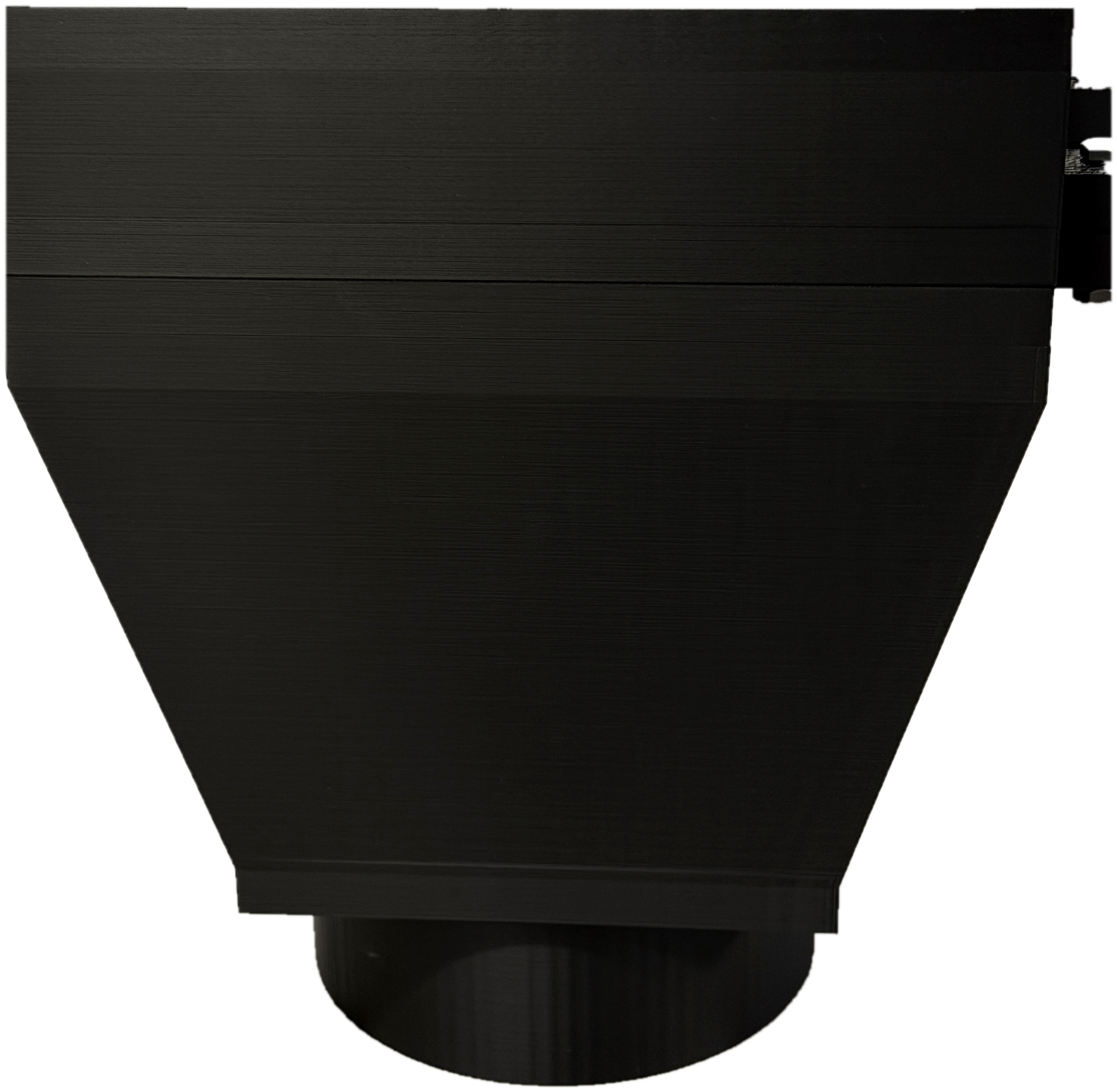
P1 CAD & Assembly
Exploded CAD view
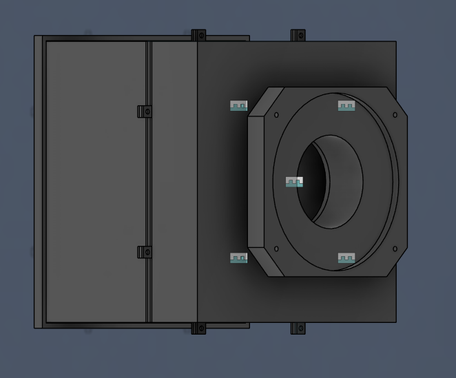
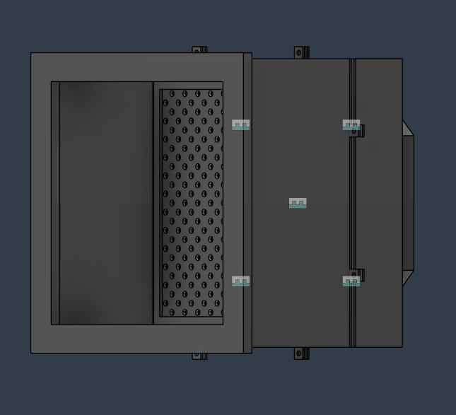
Physical assembly
P1 — tapered outlet section
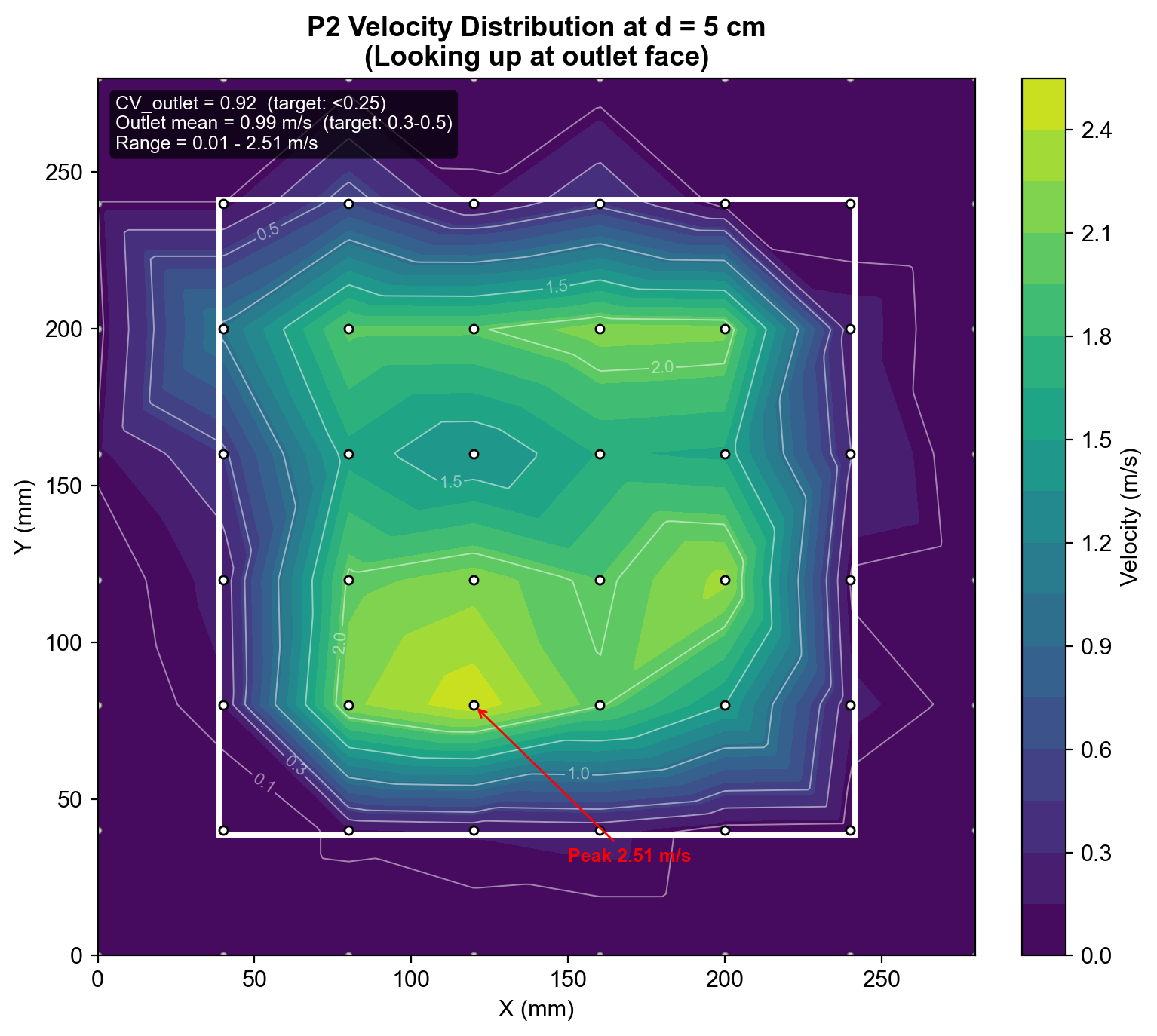
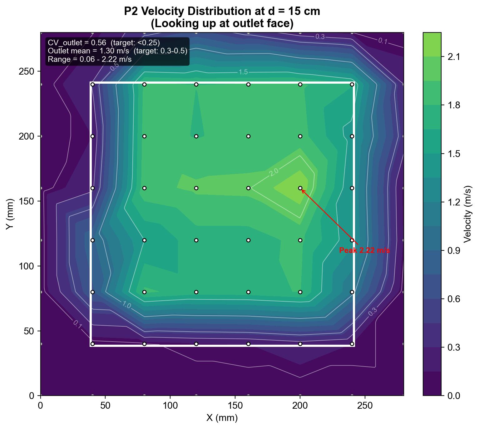
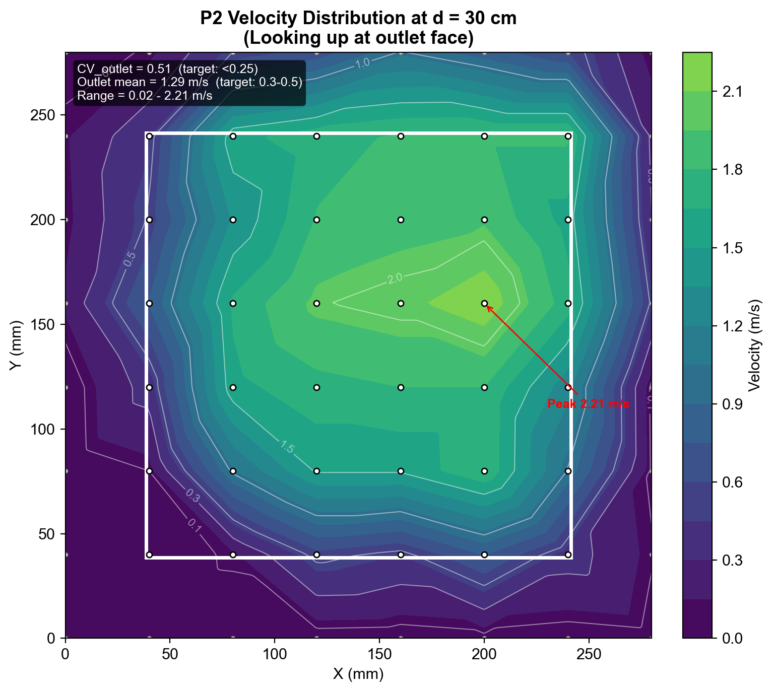
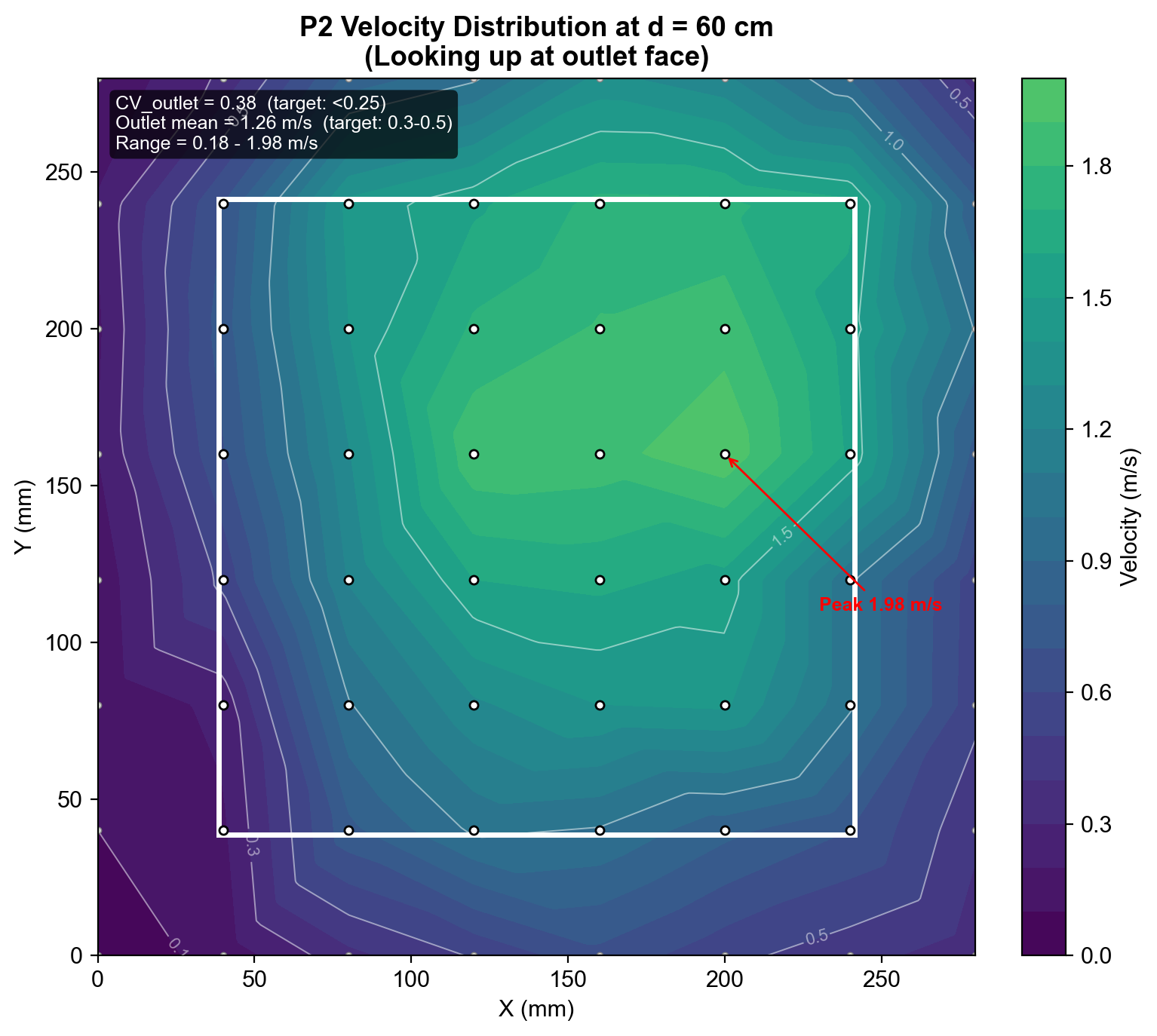
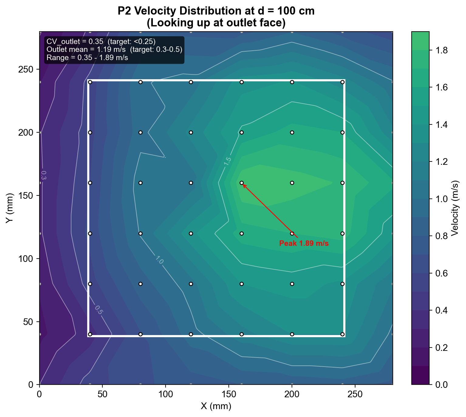
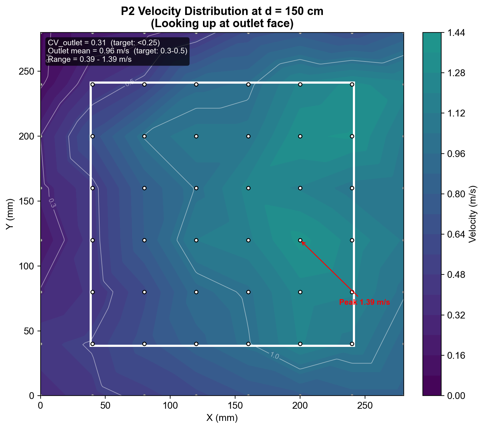
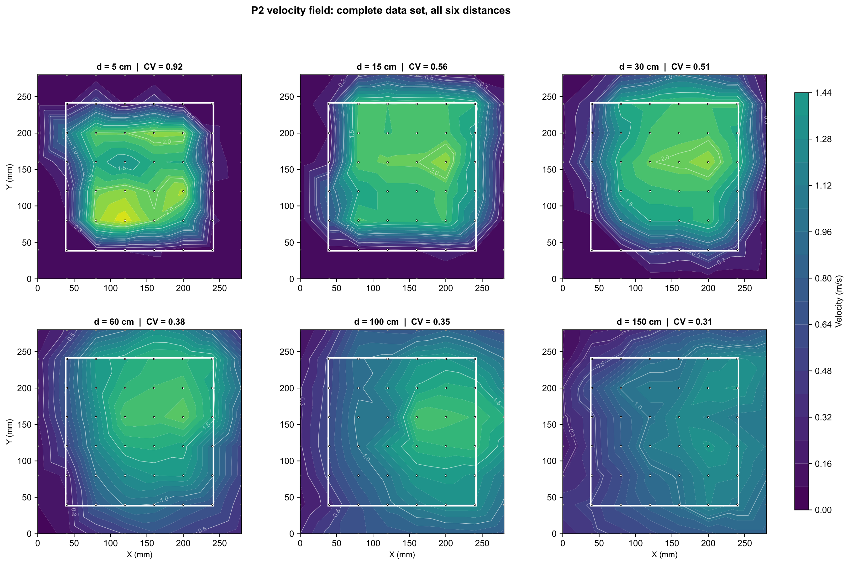
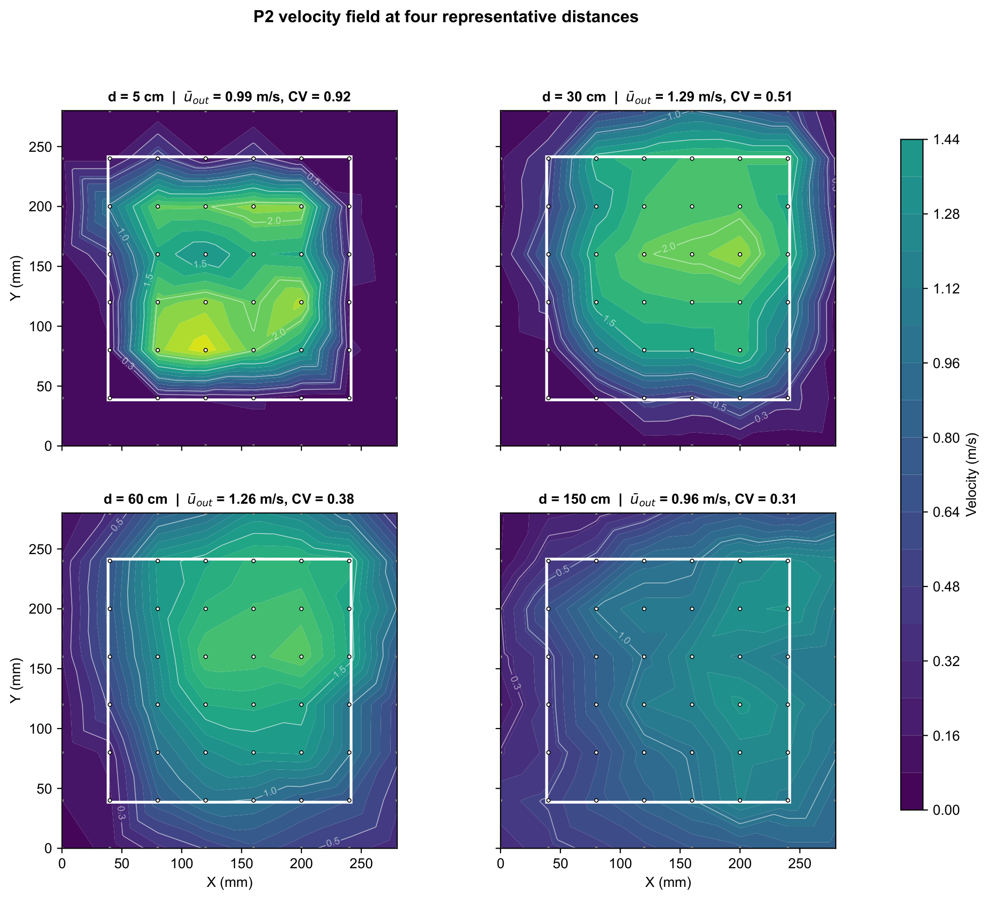
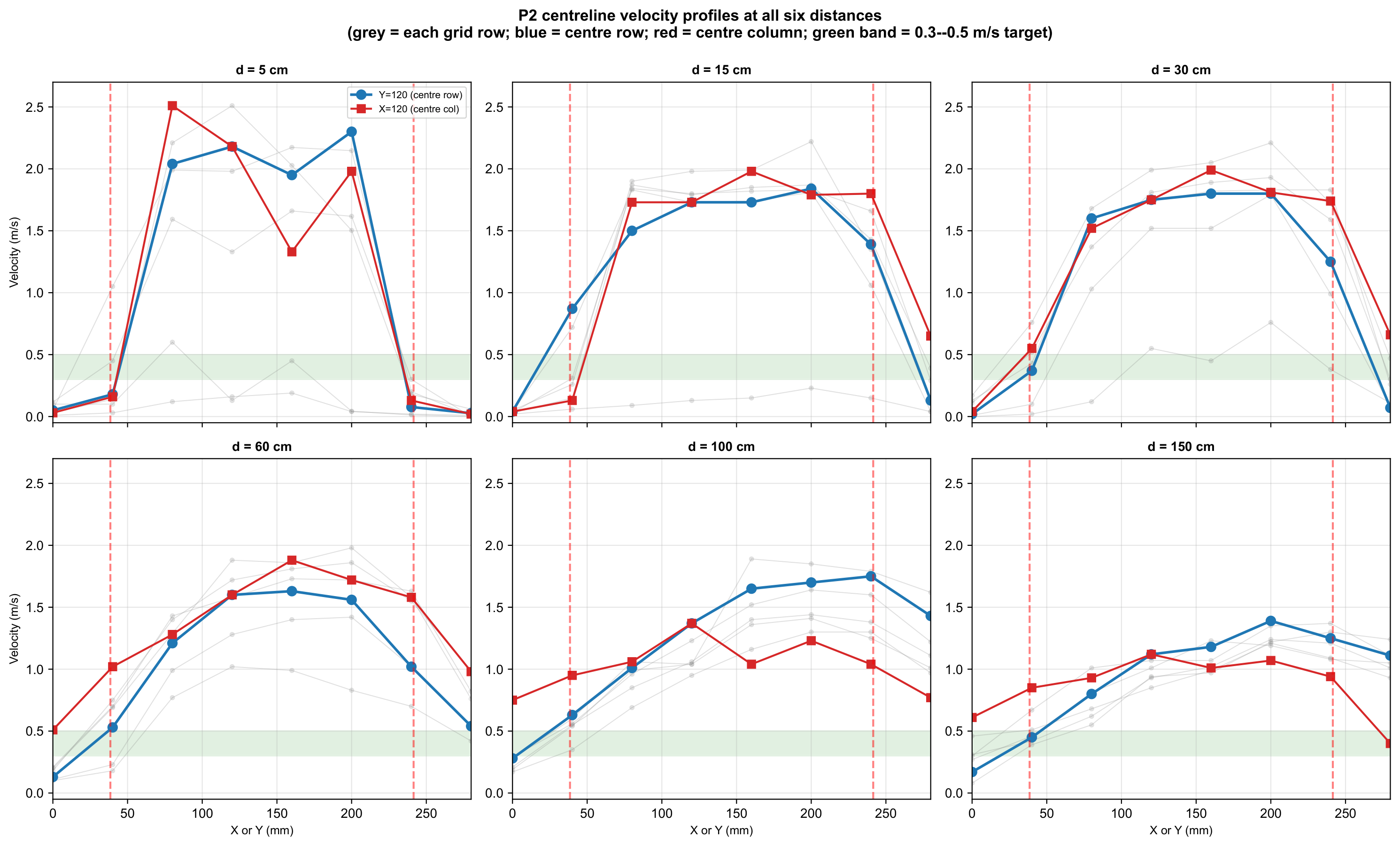
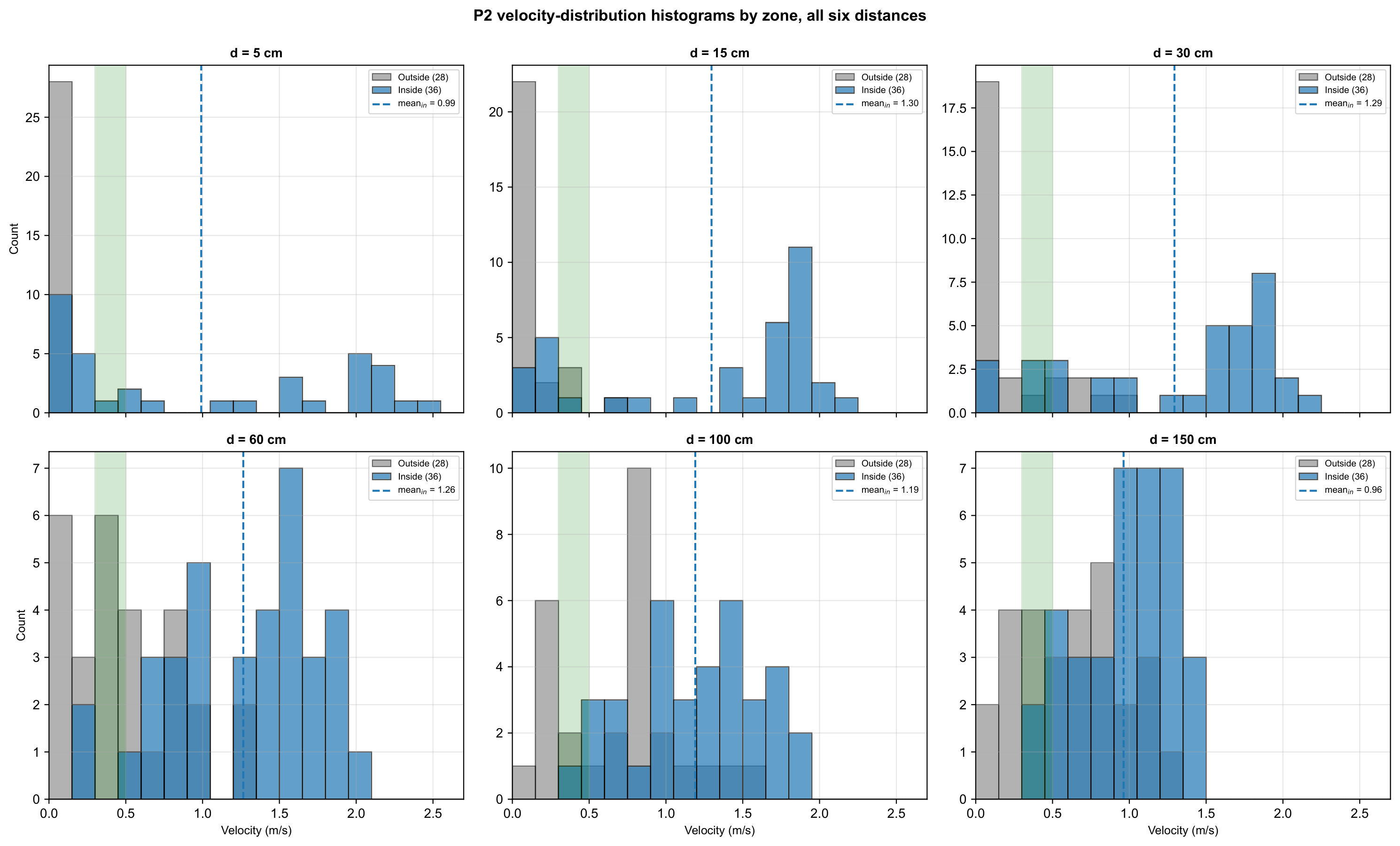
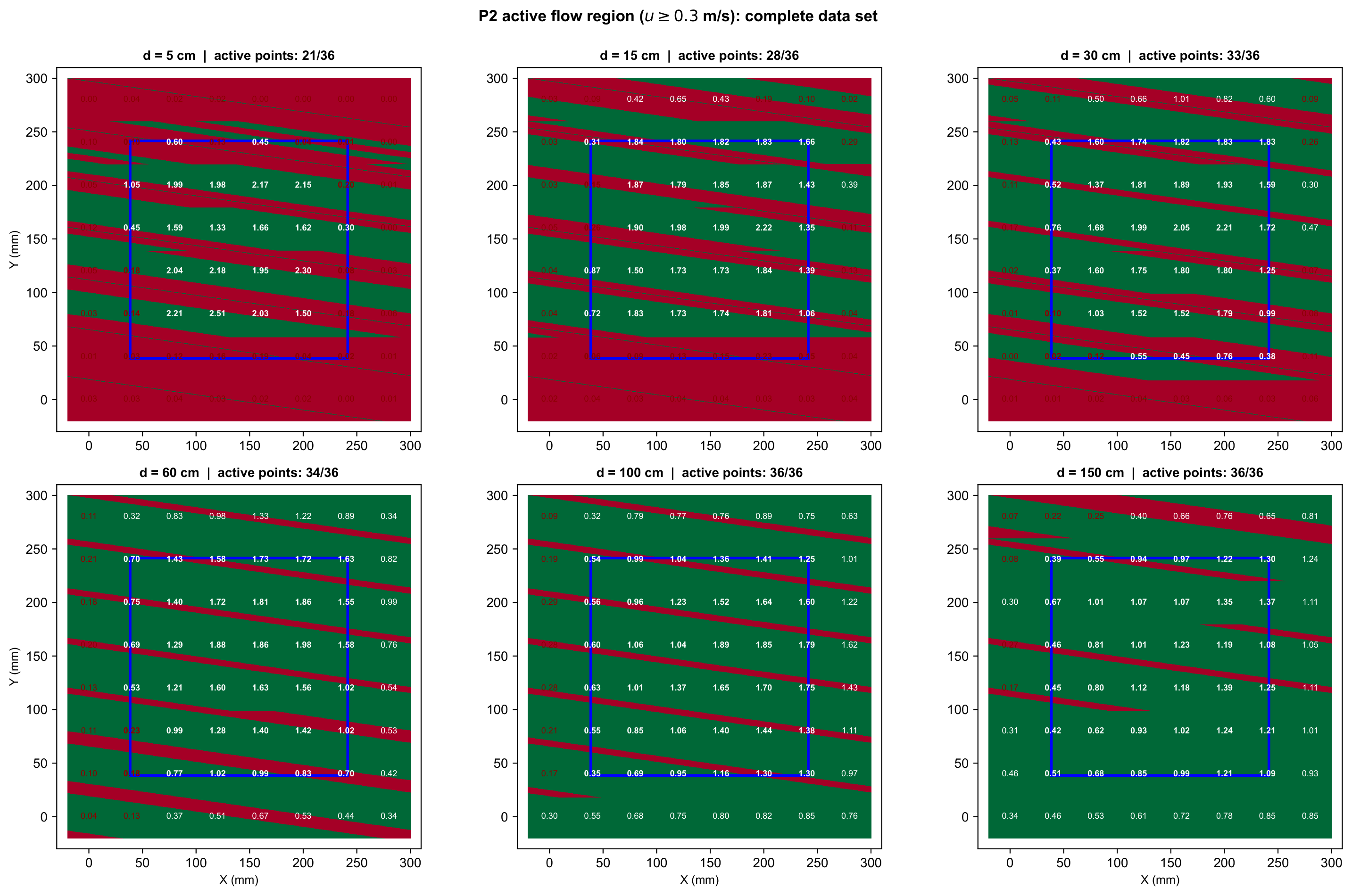
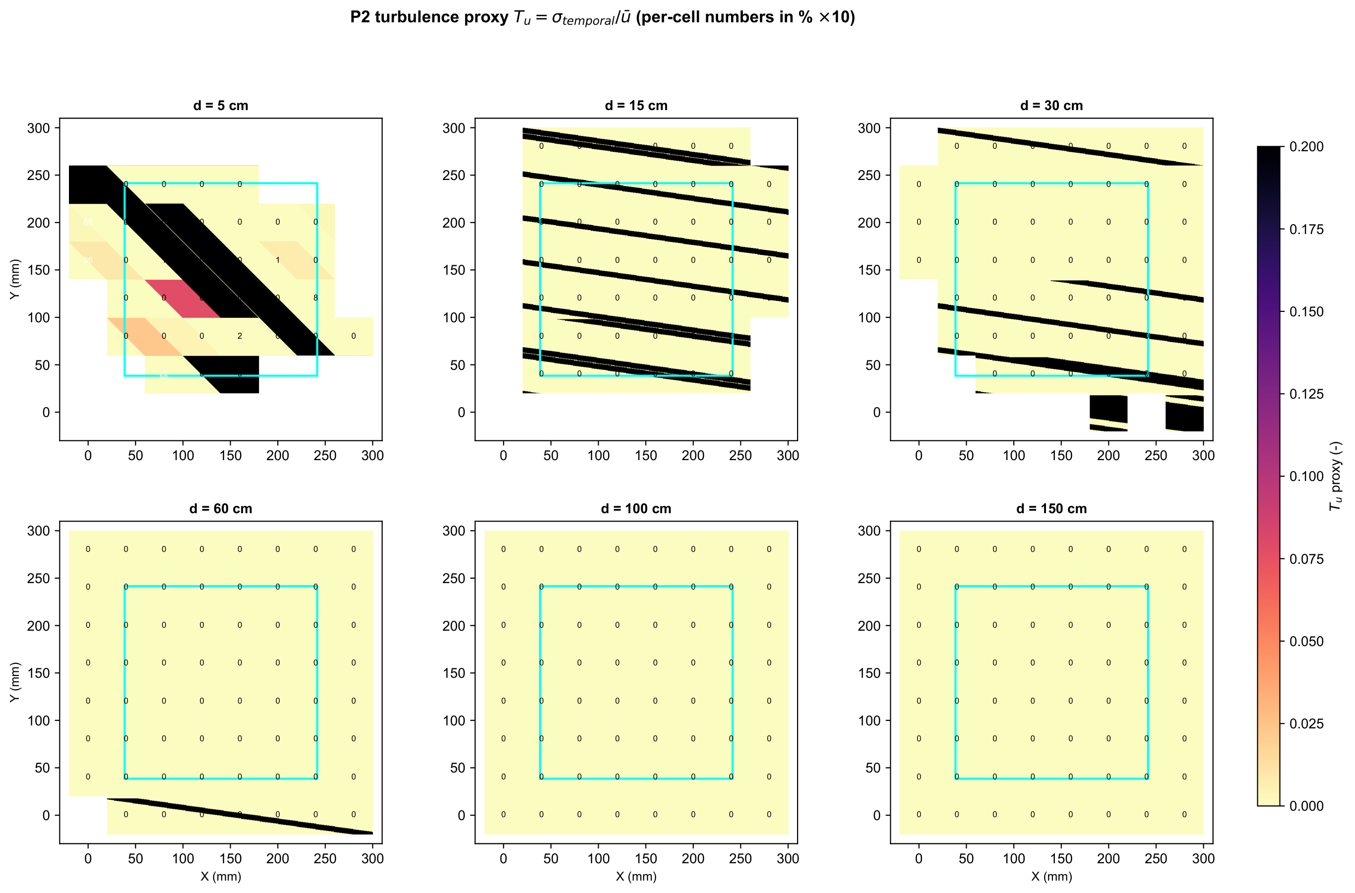
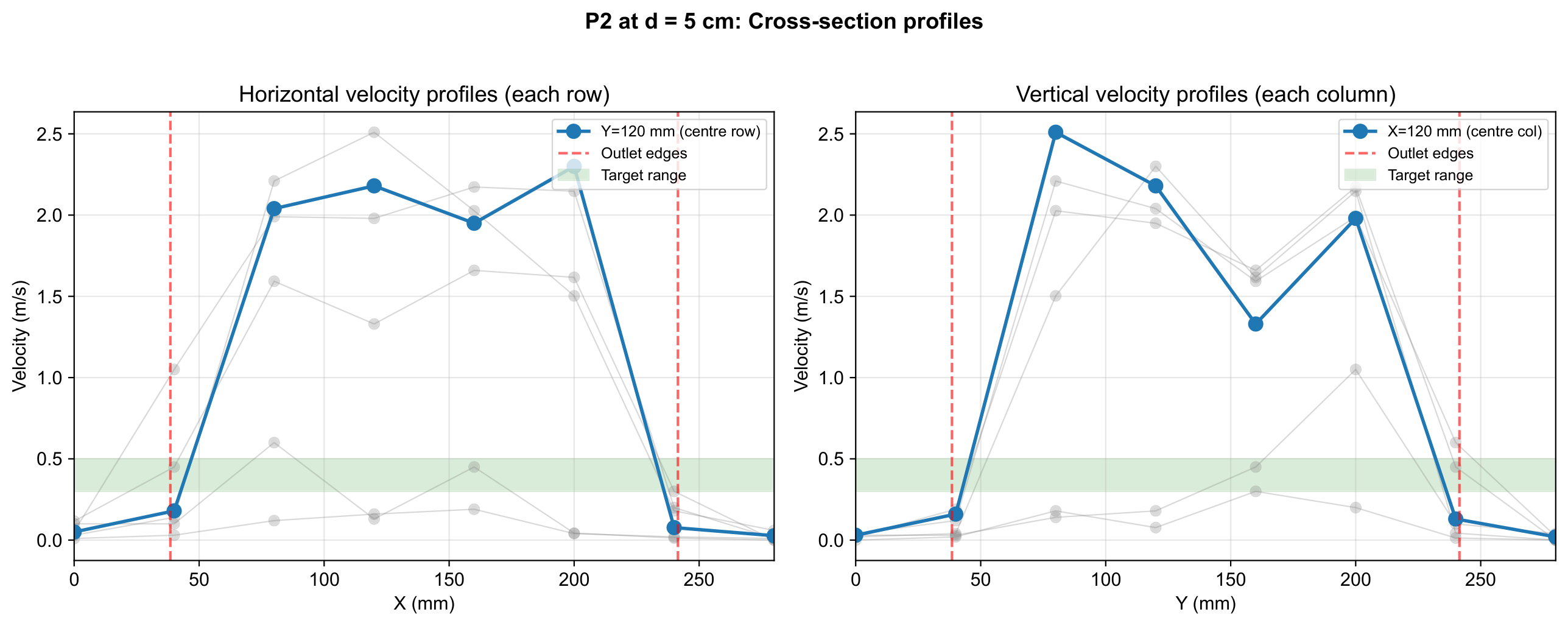
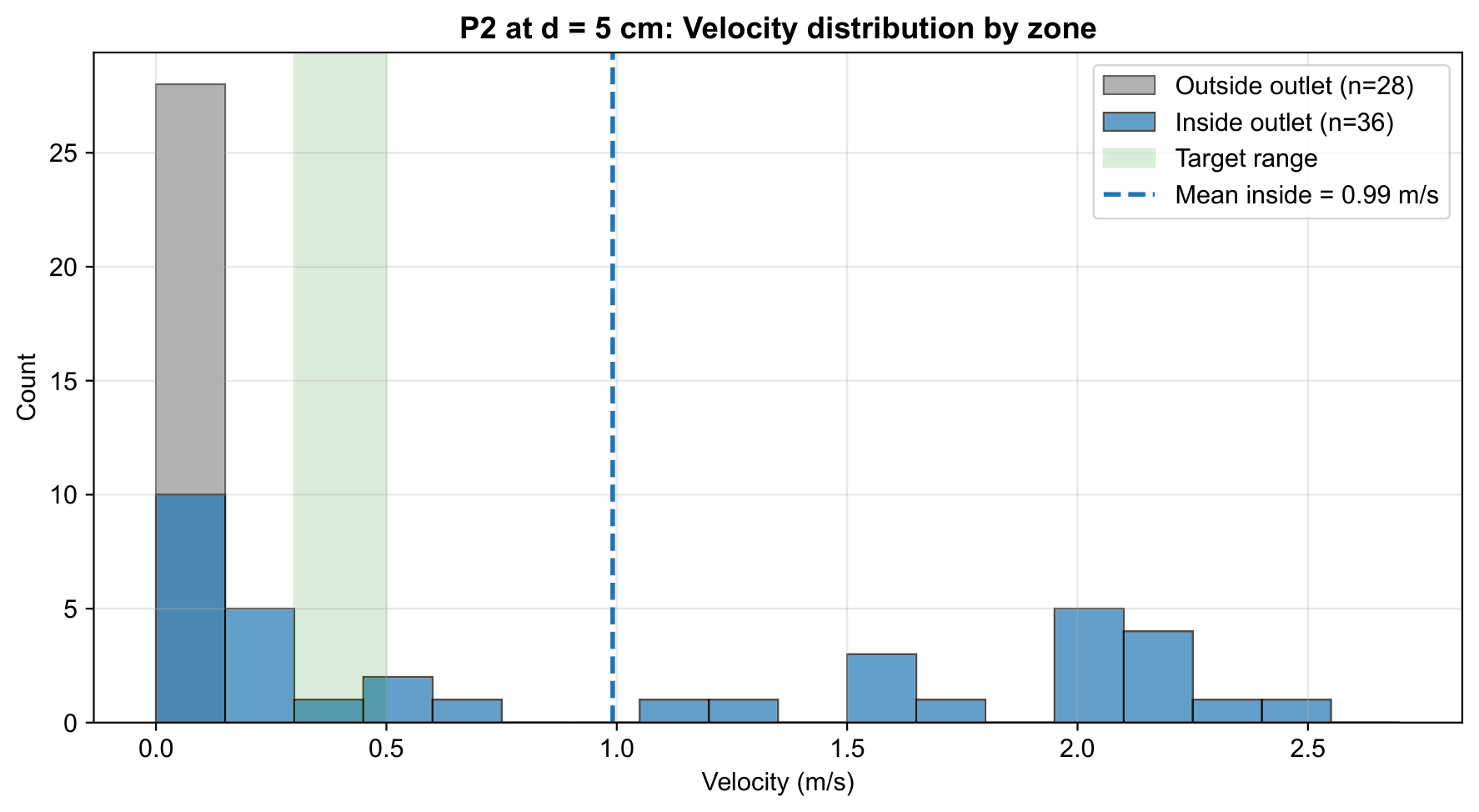
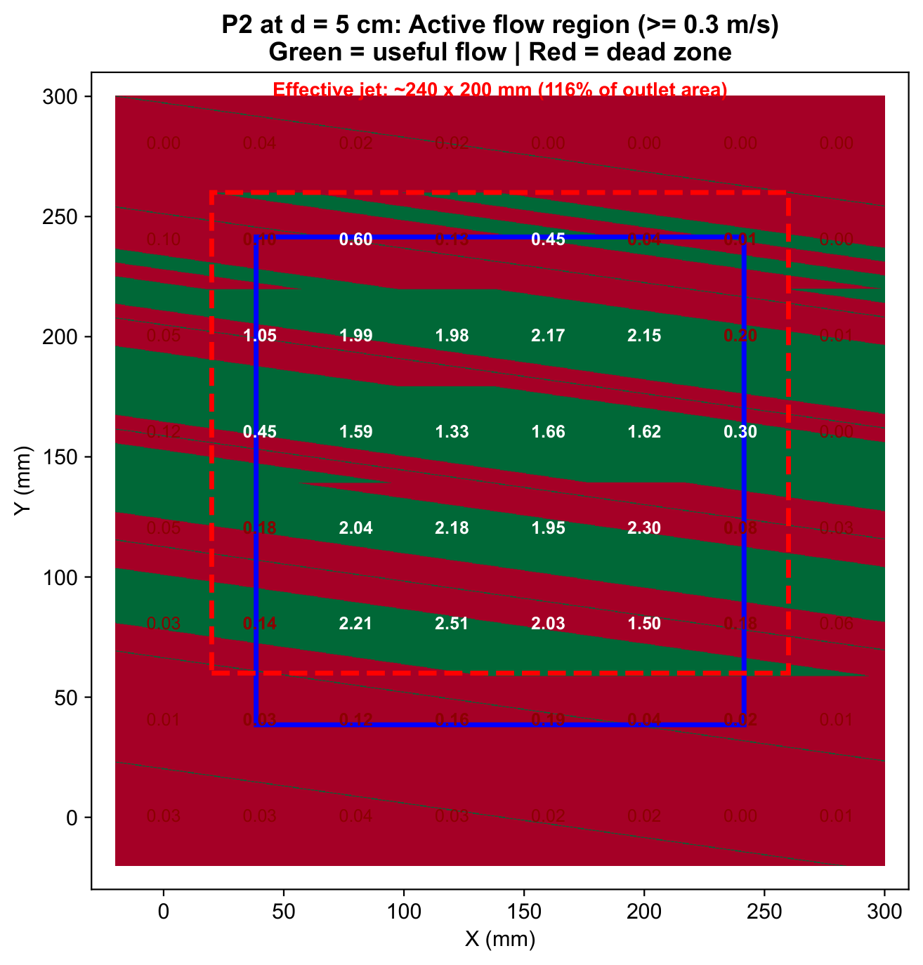
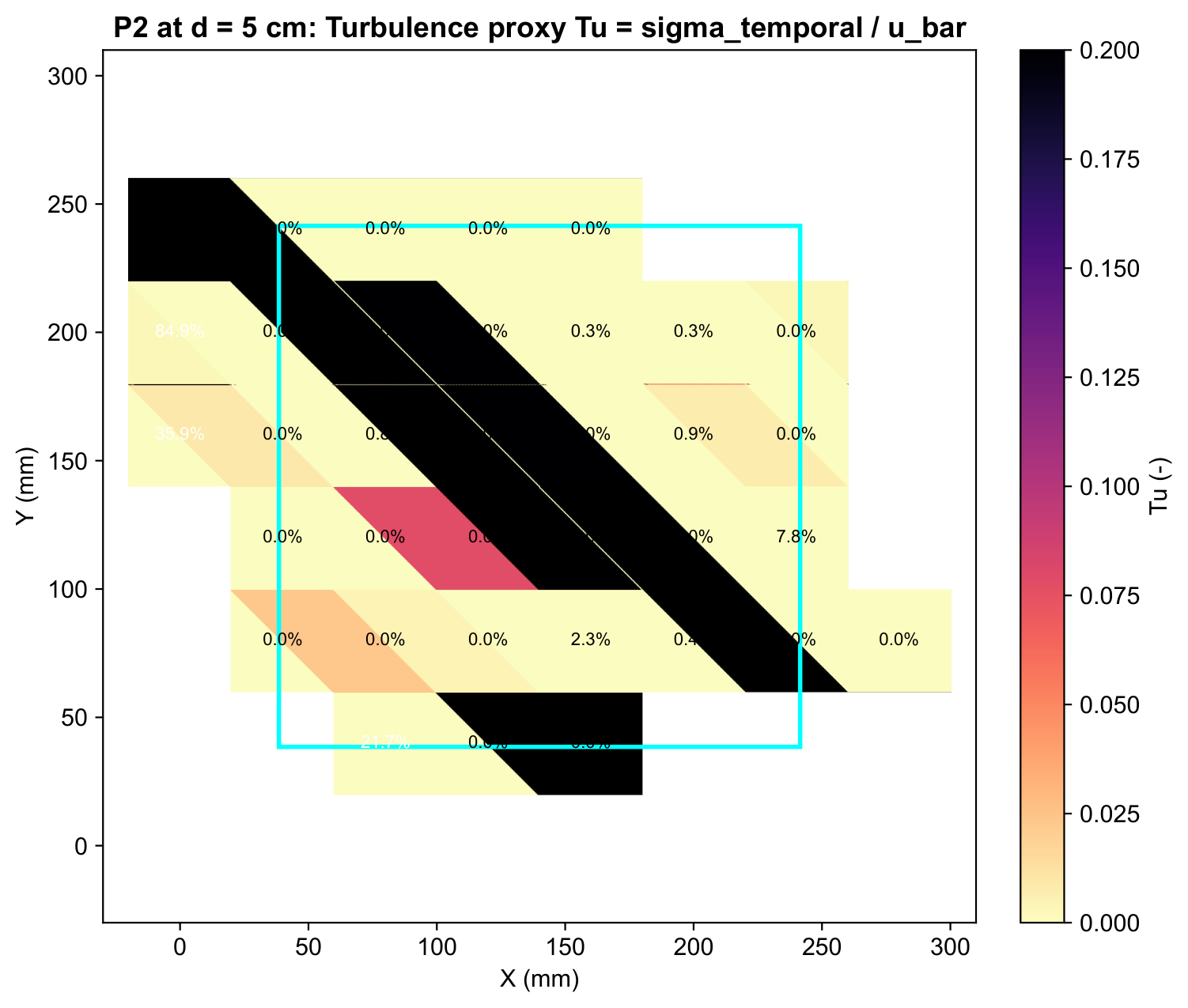
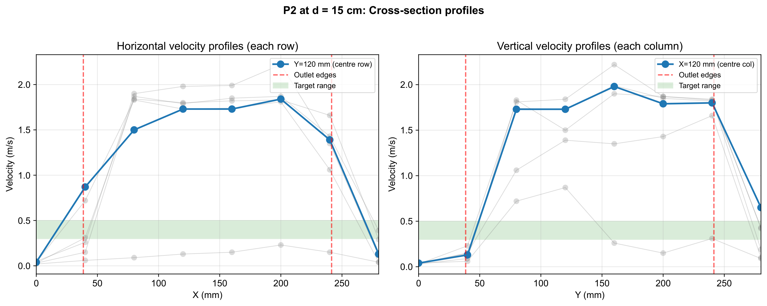
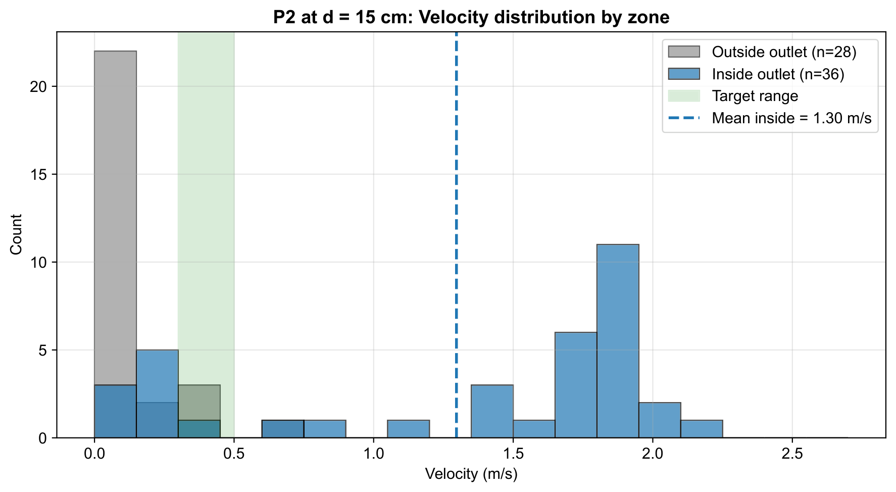
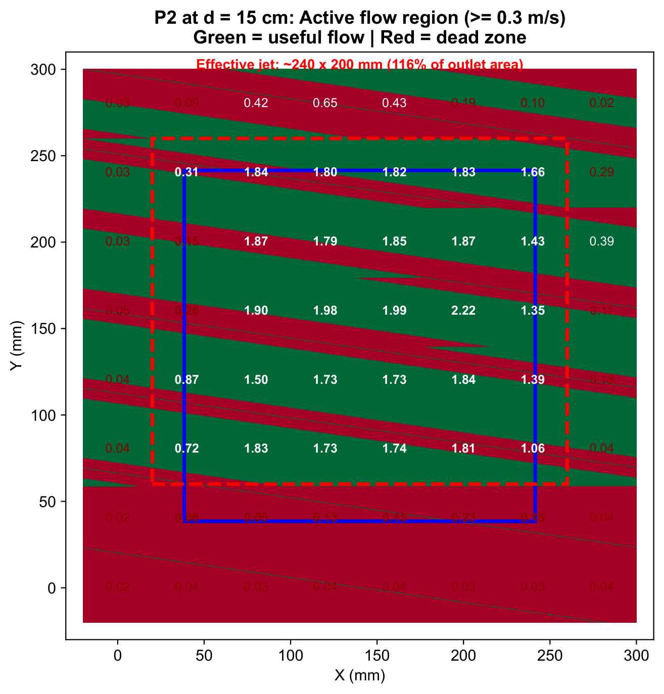
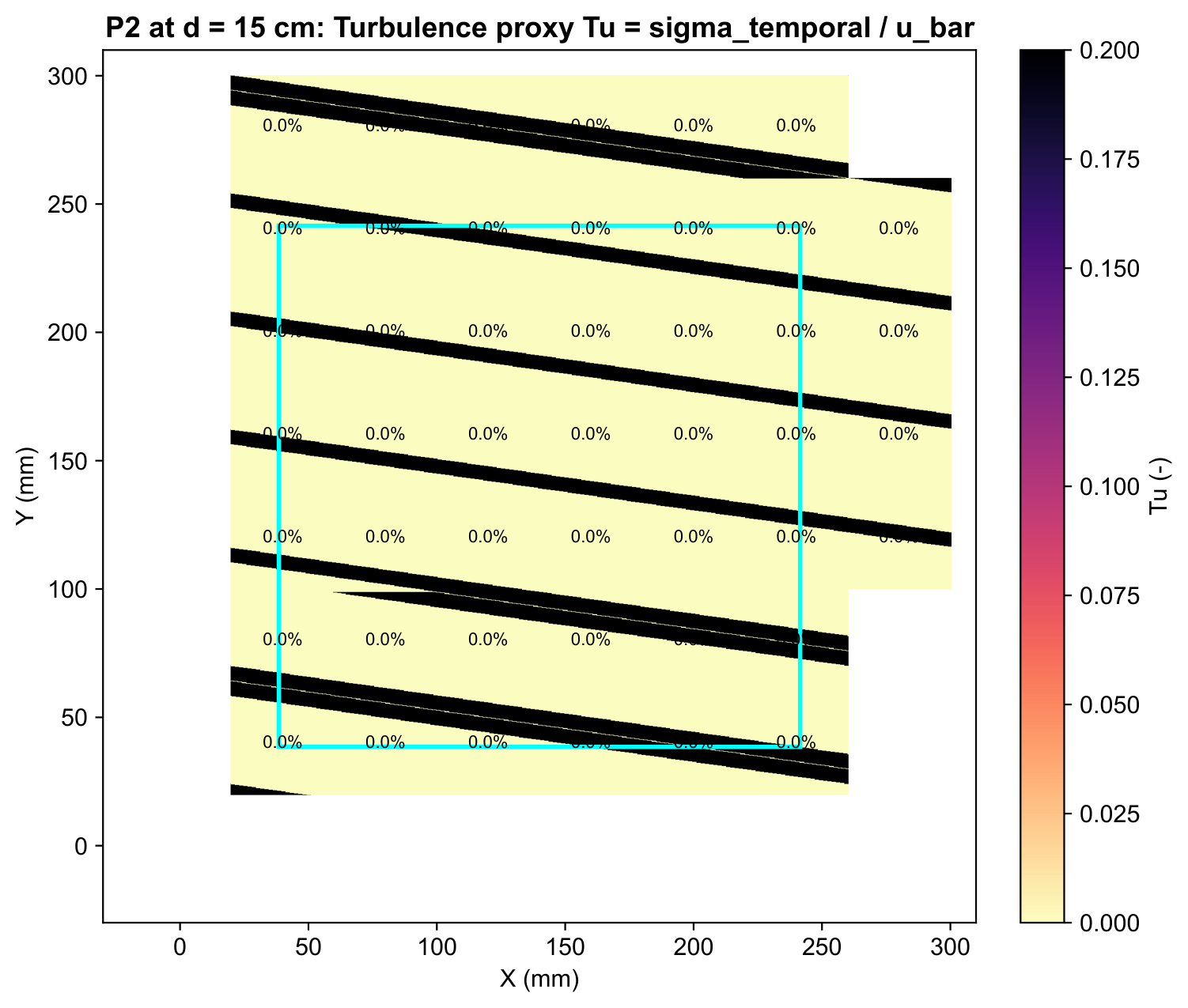
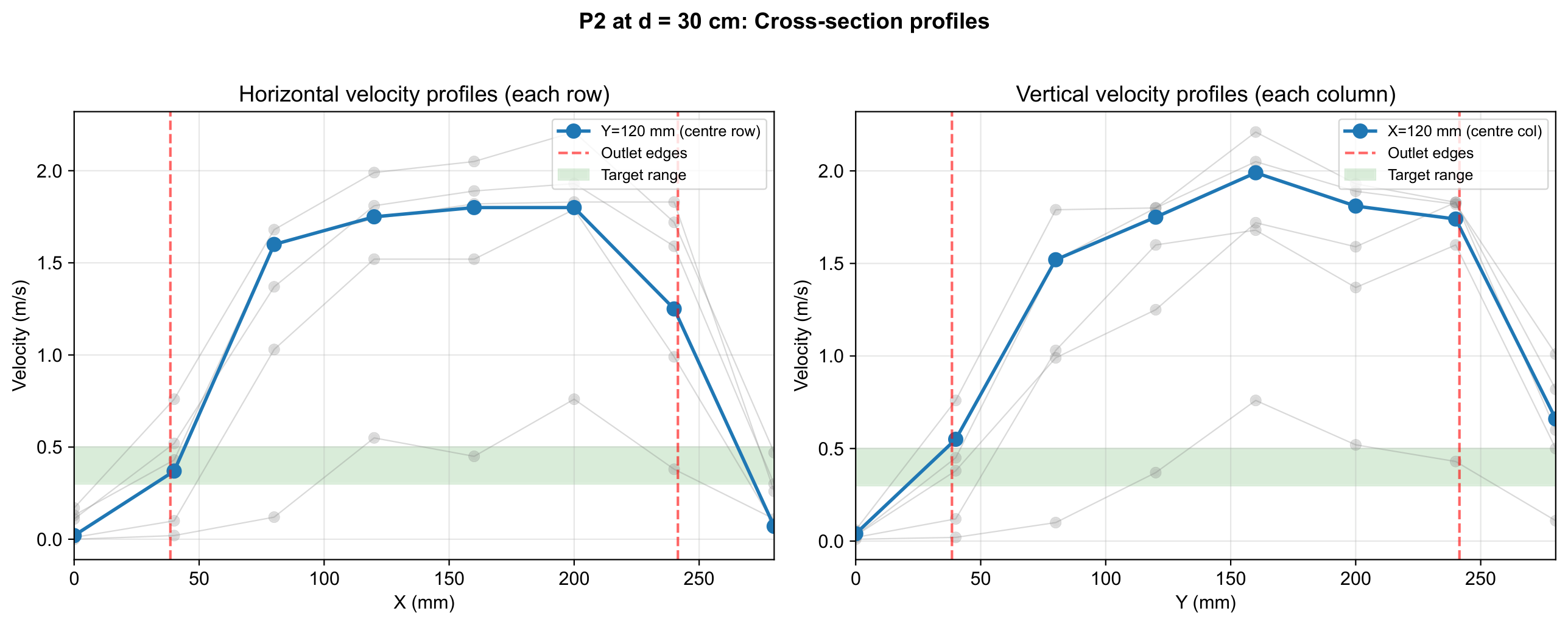
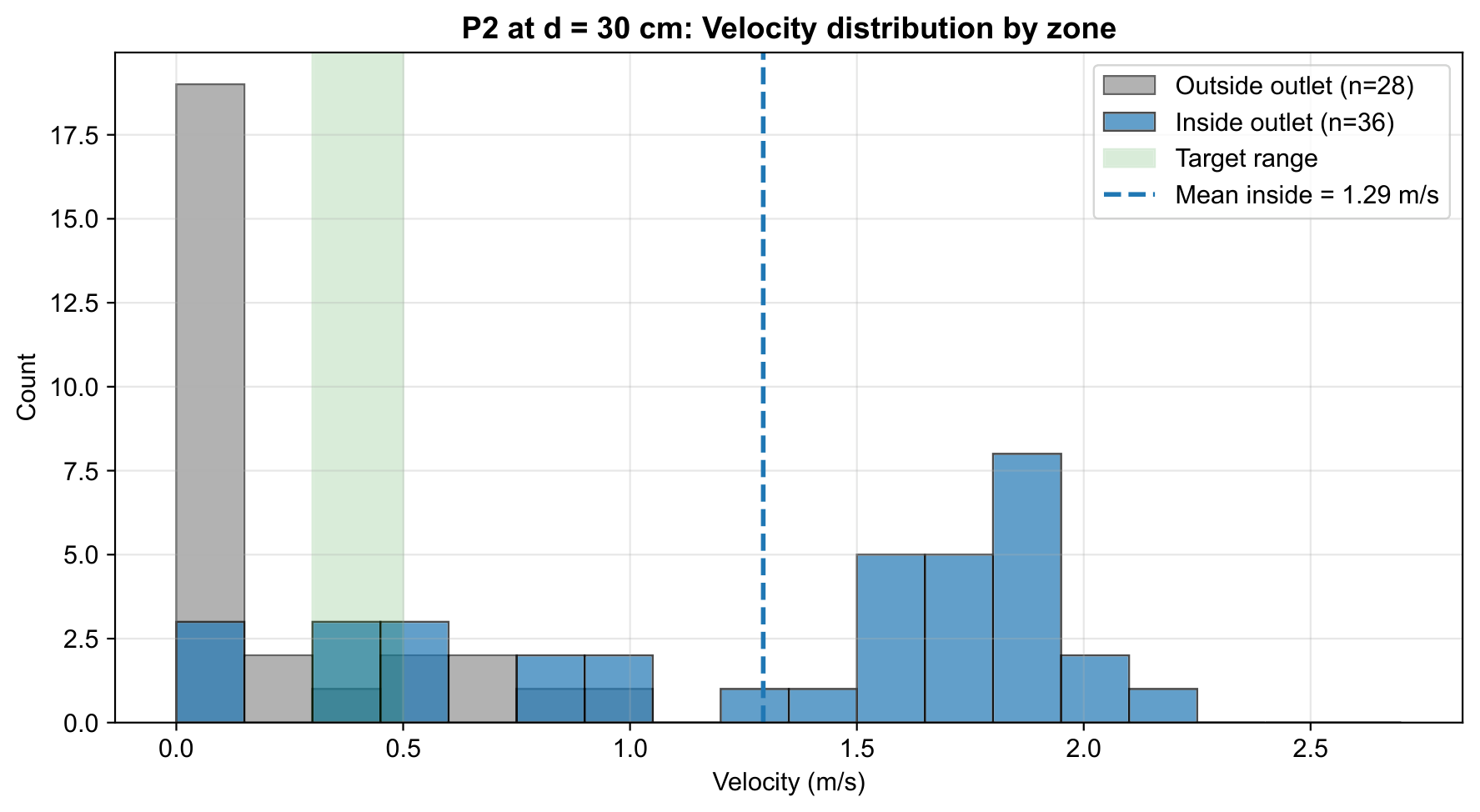
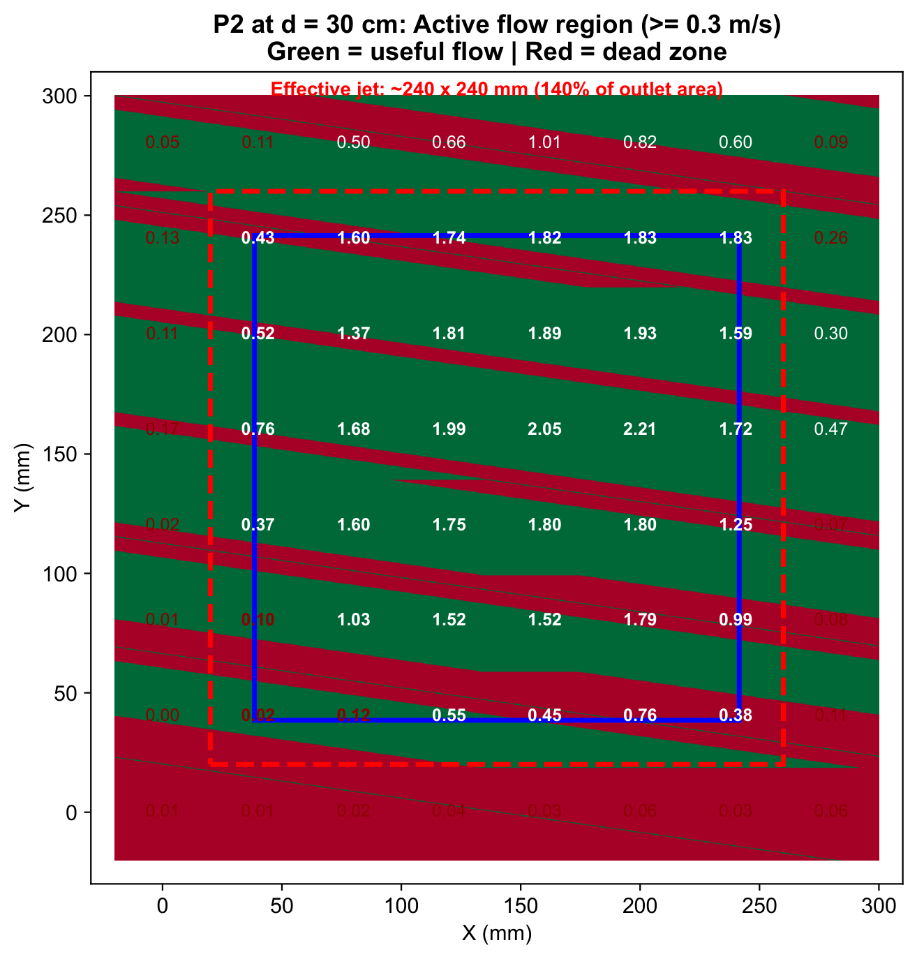
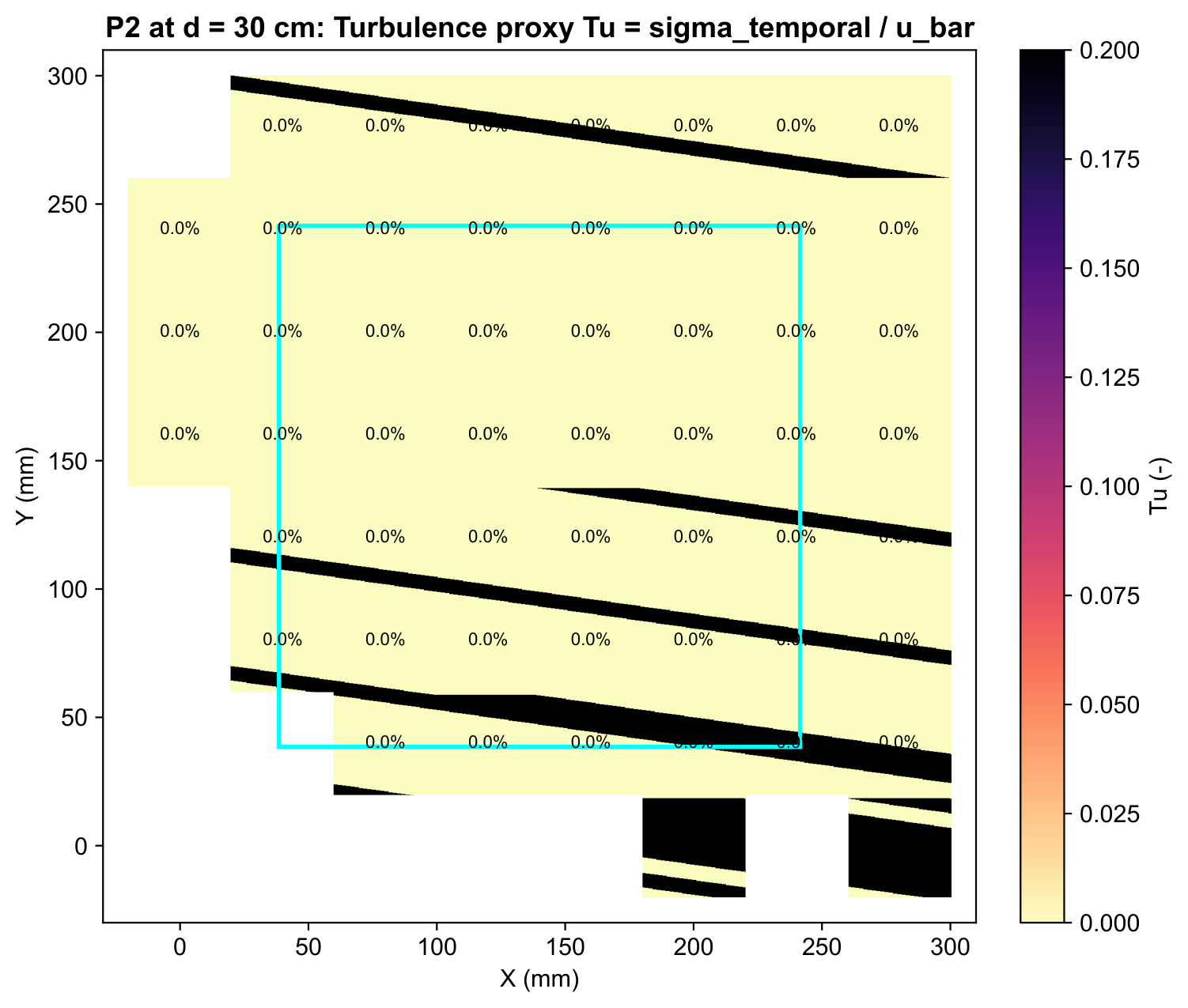
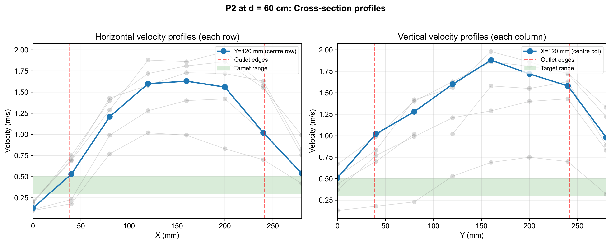
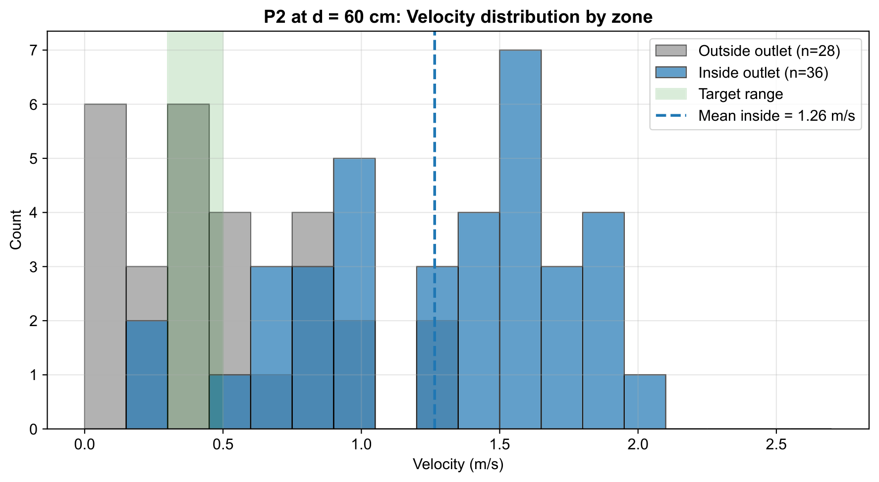
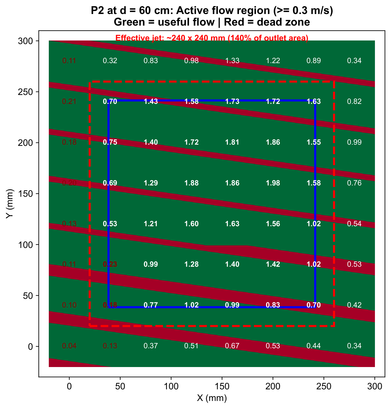
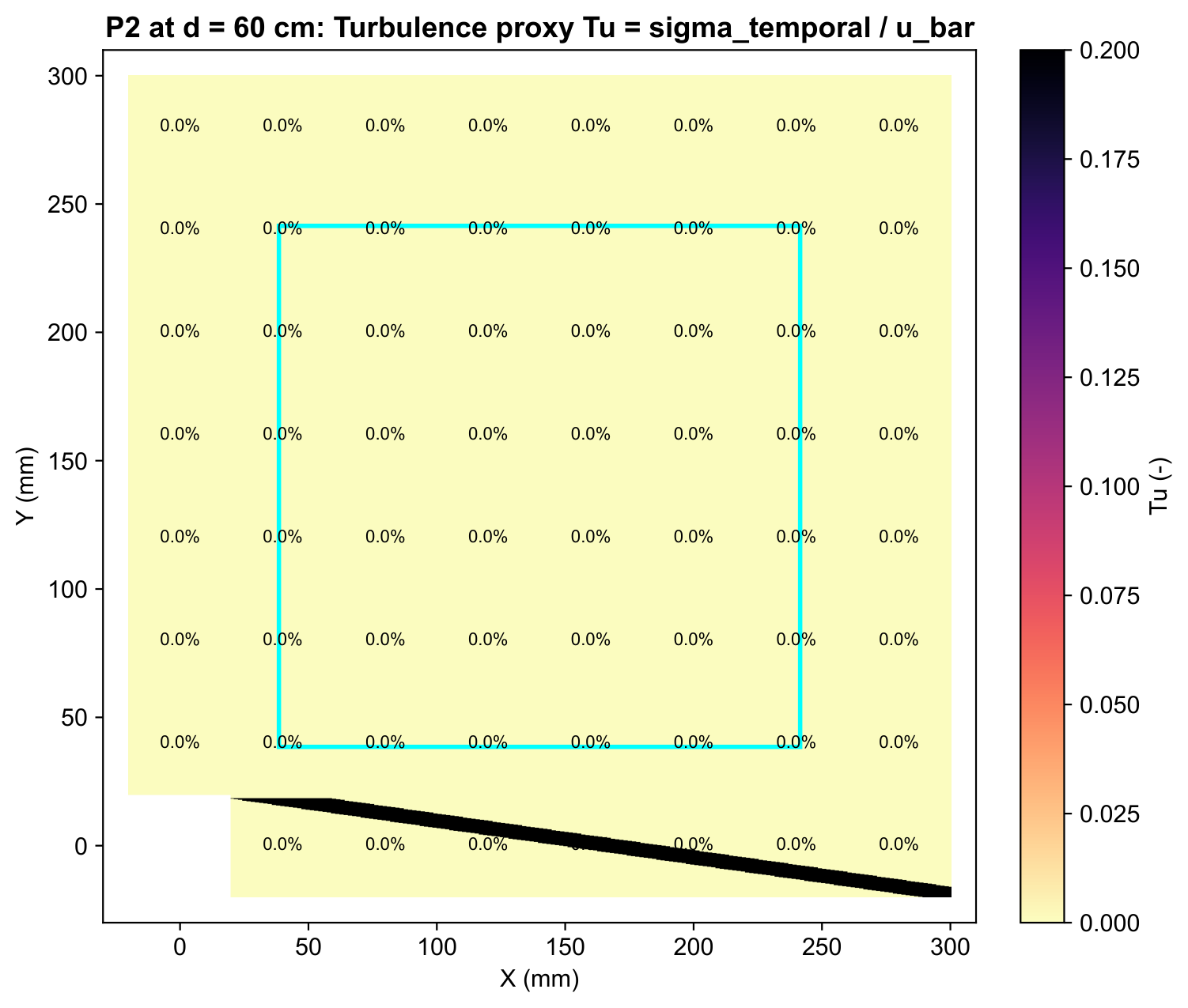
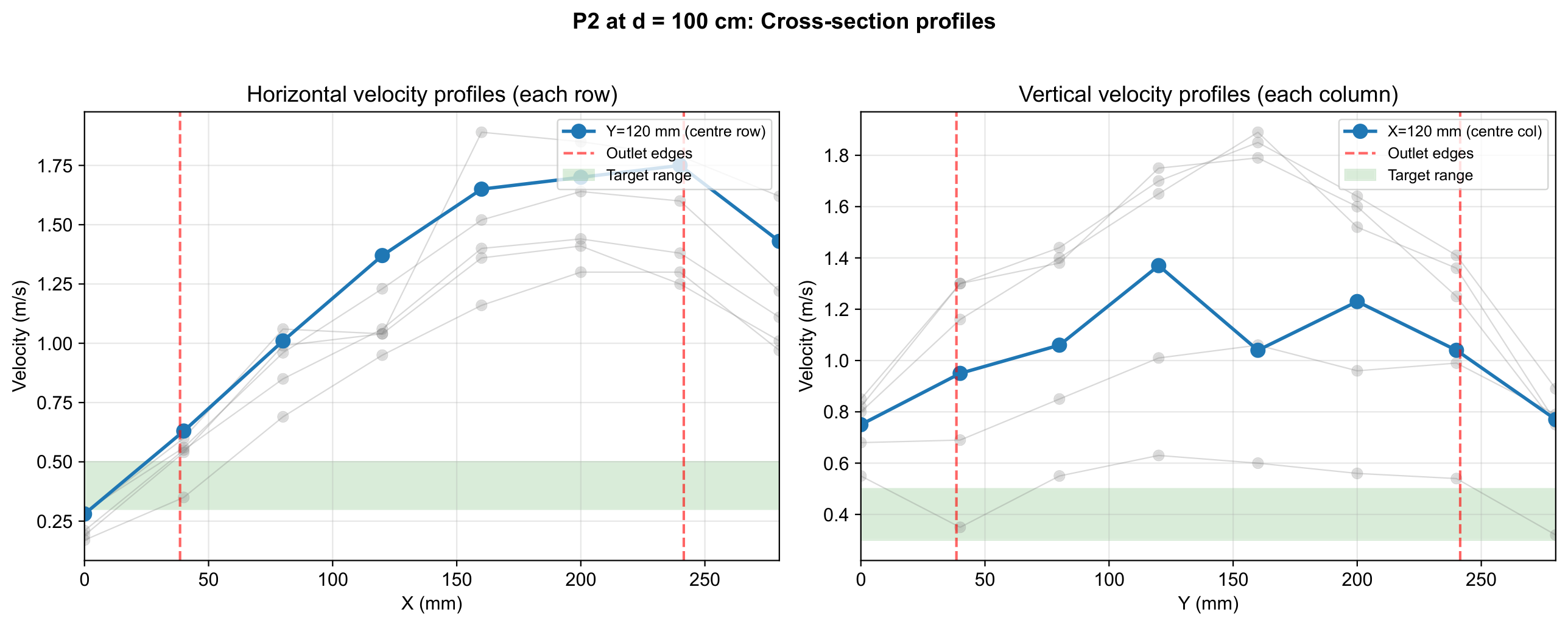
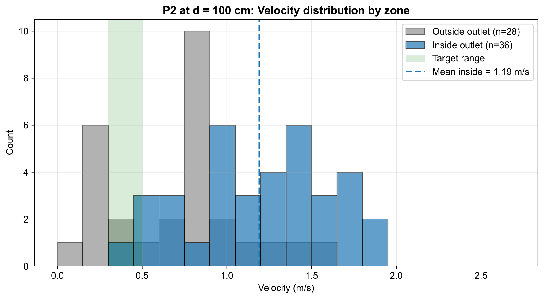
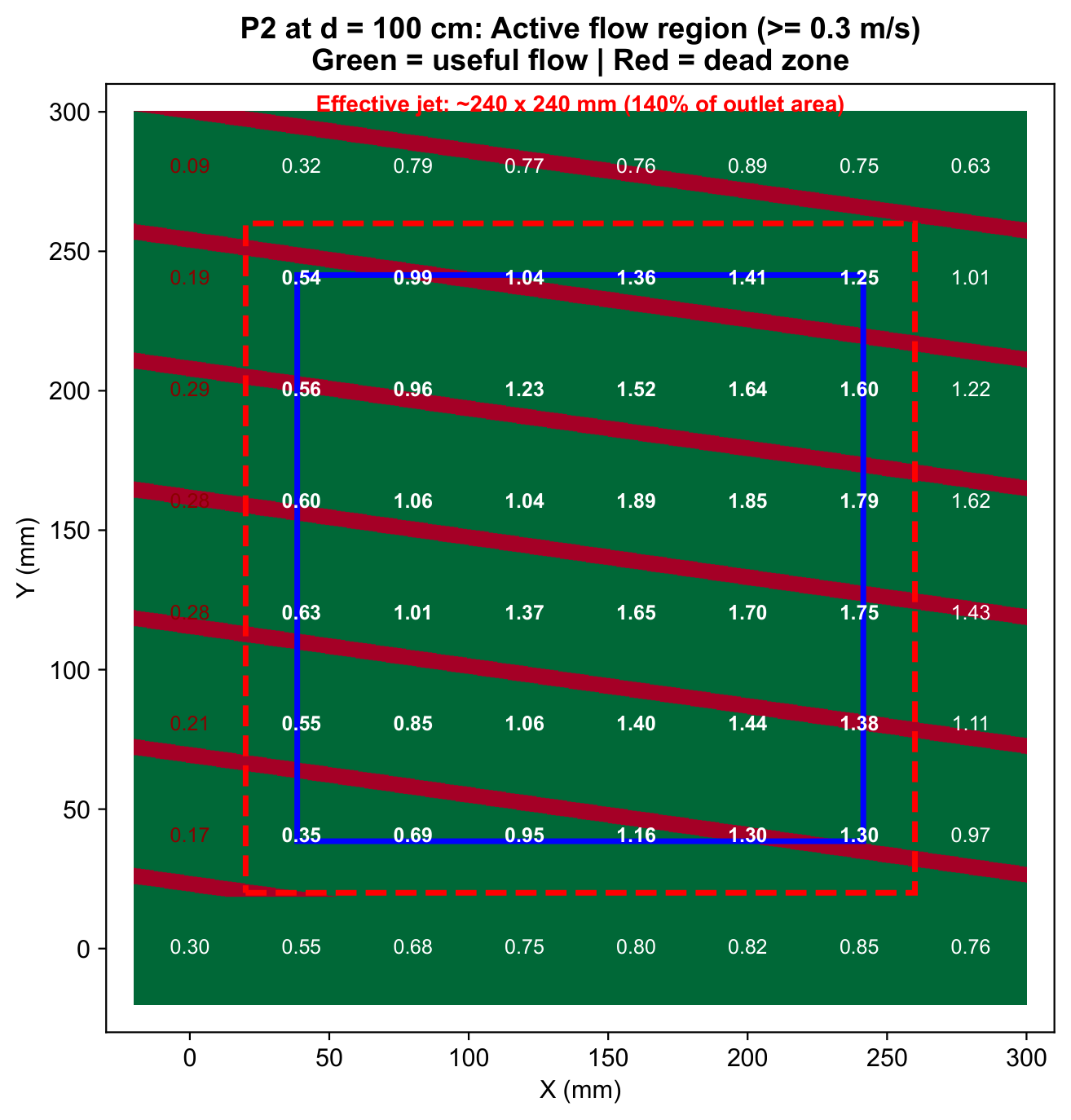
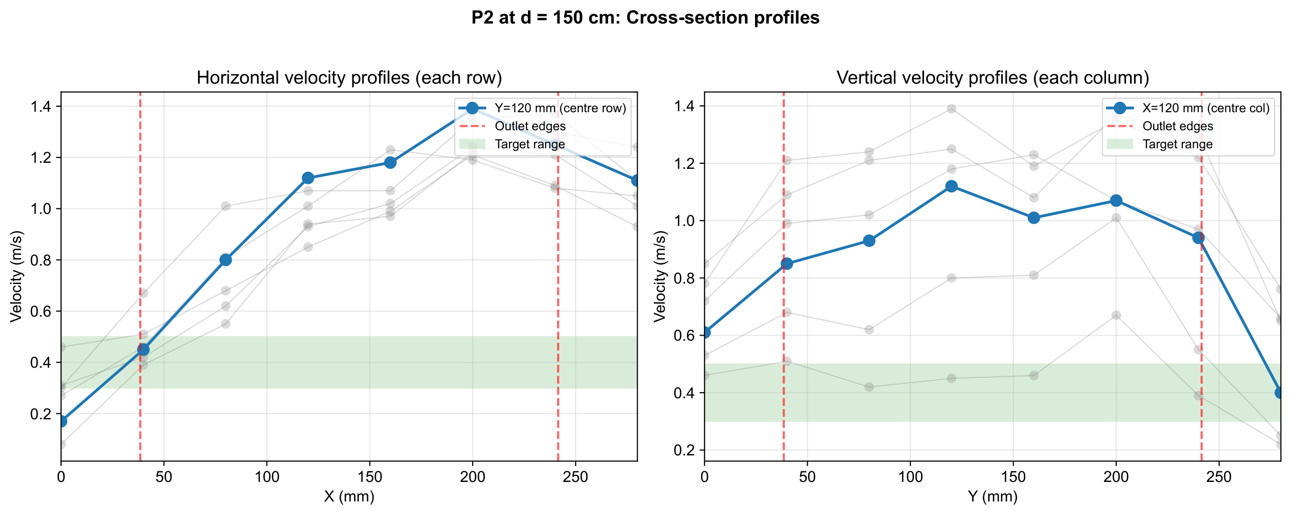
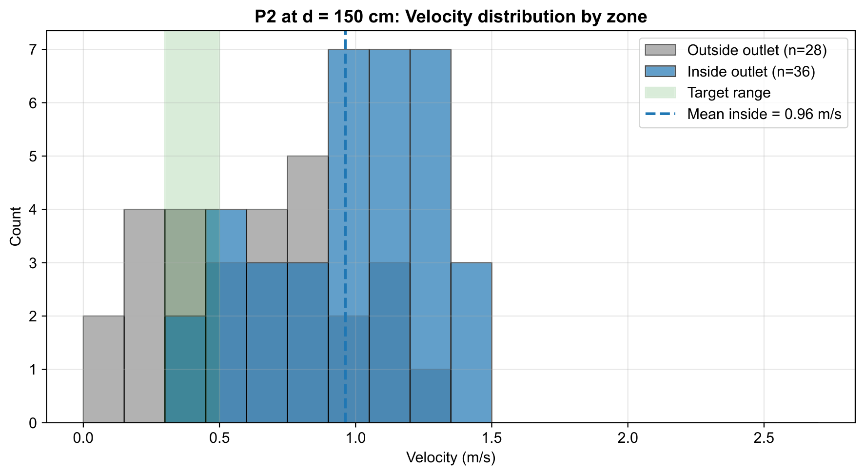
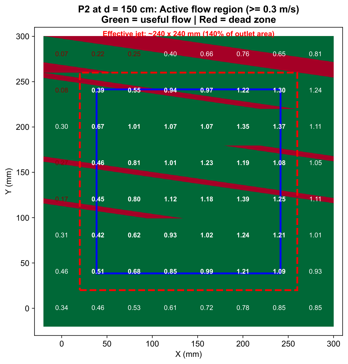
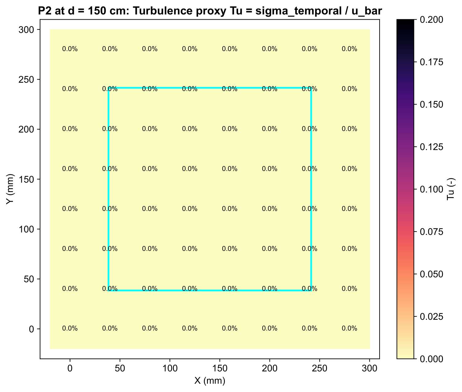
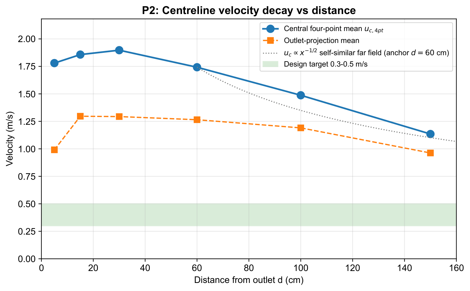
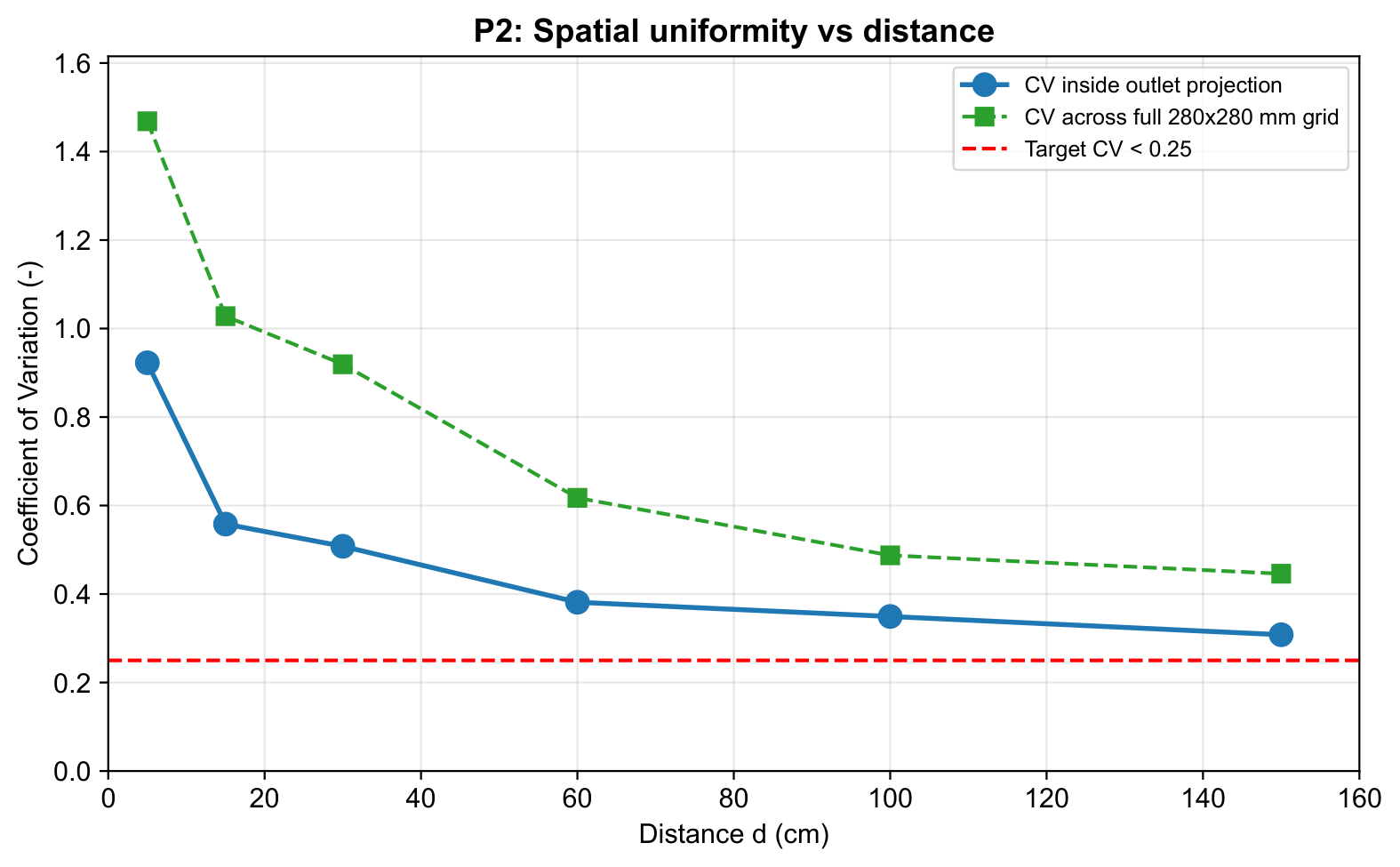
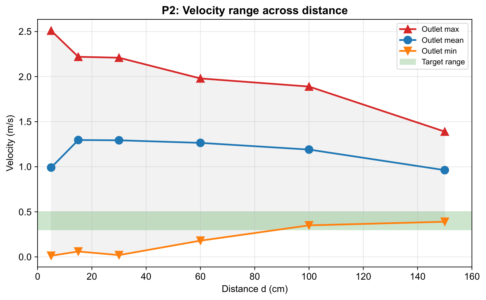
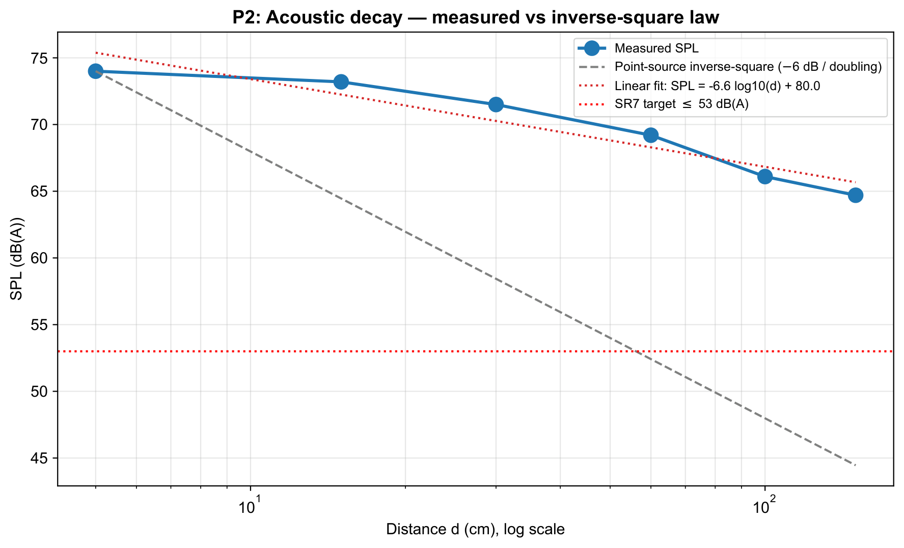
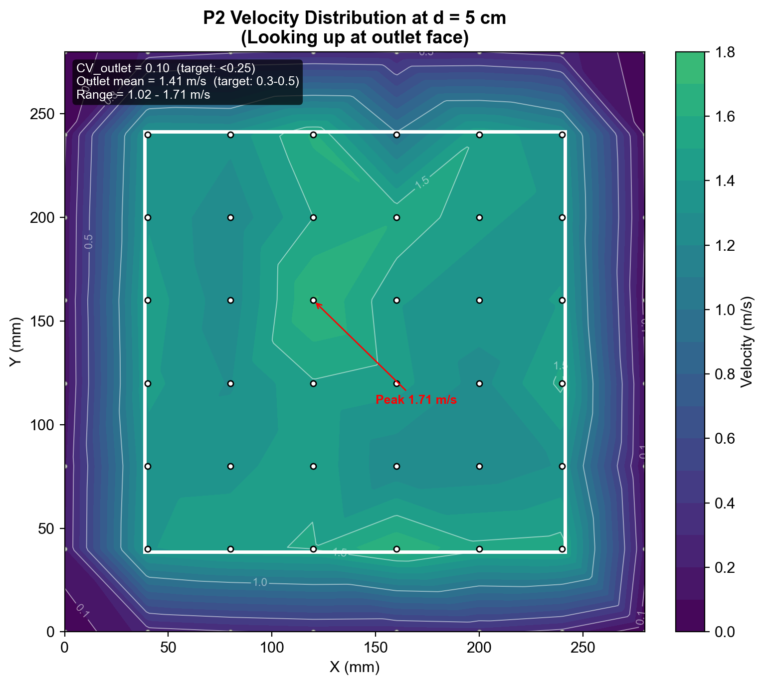
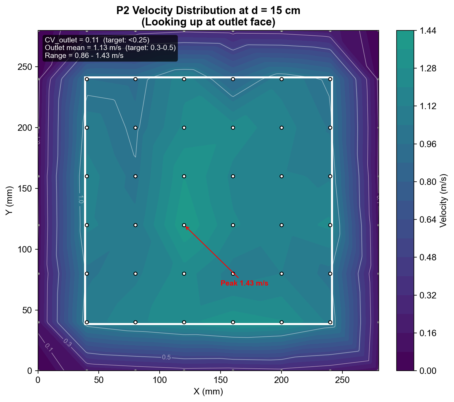
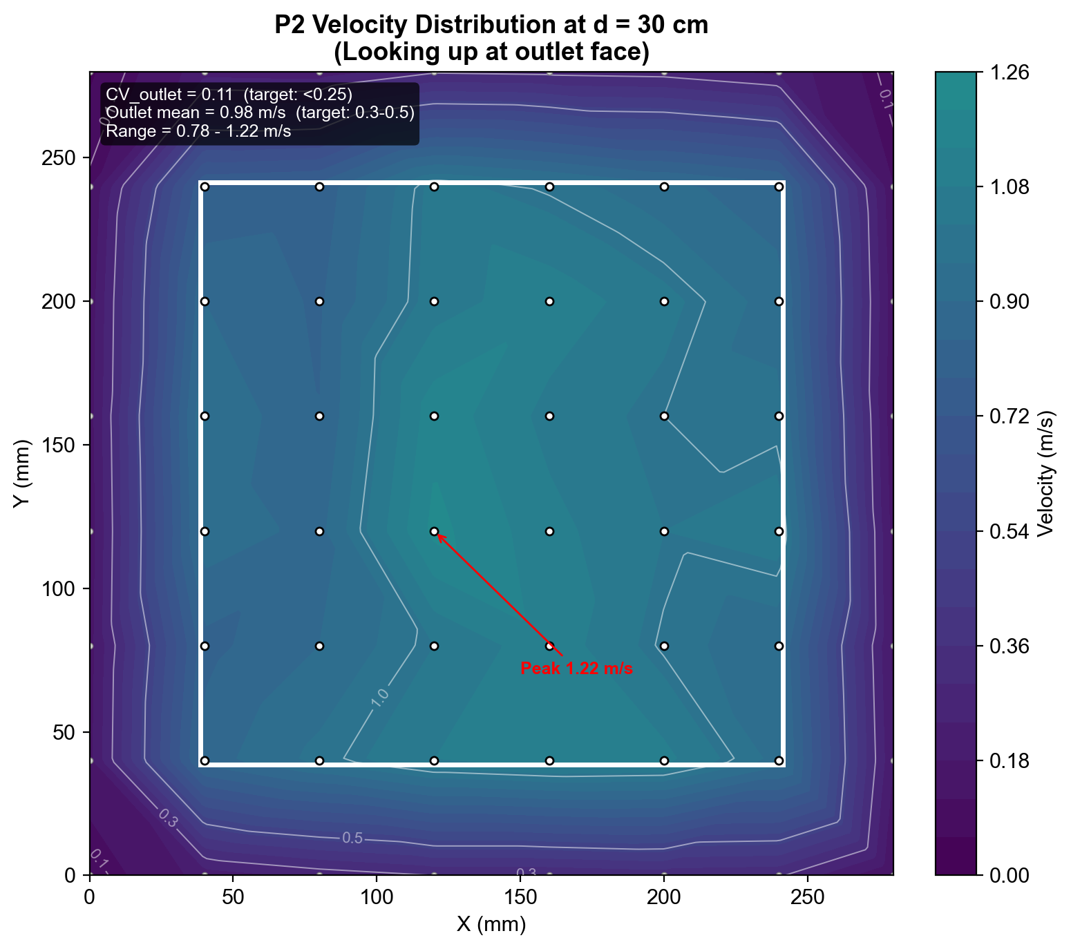
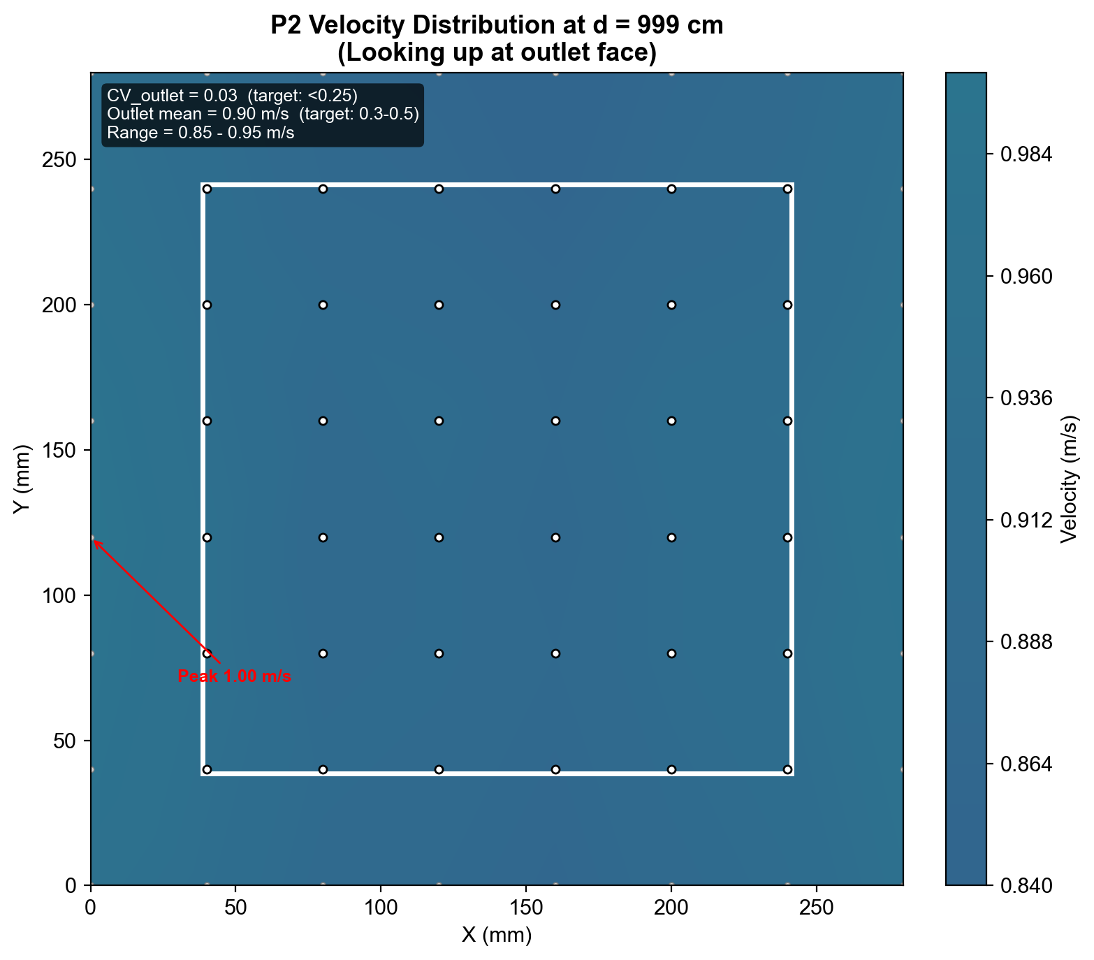
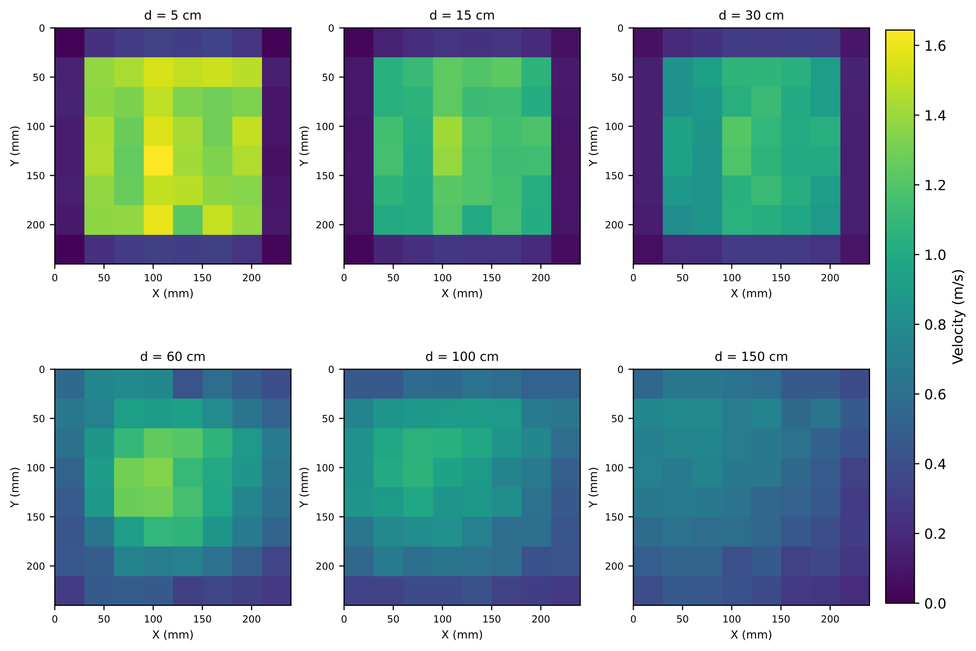
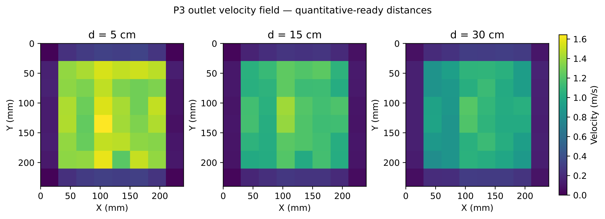
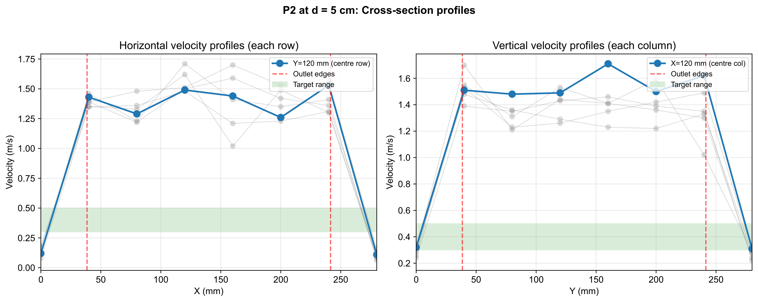
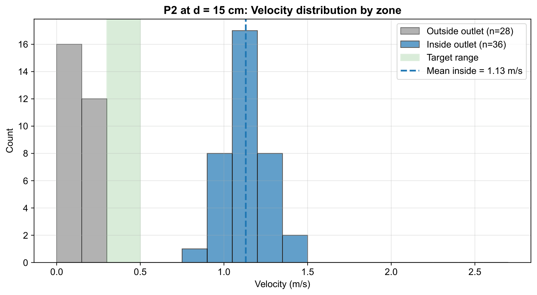
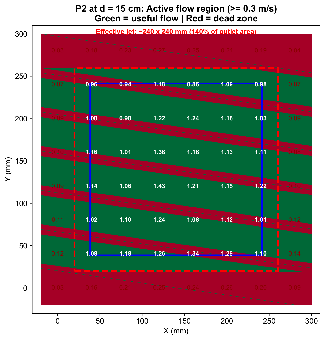
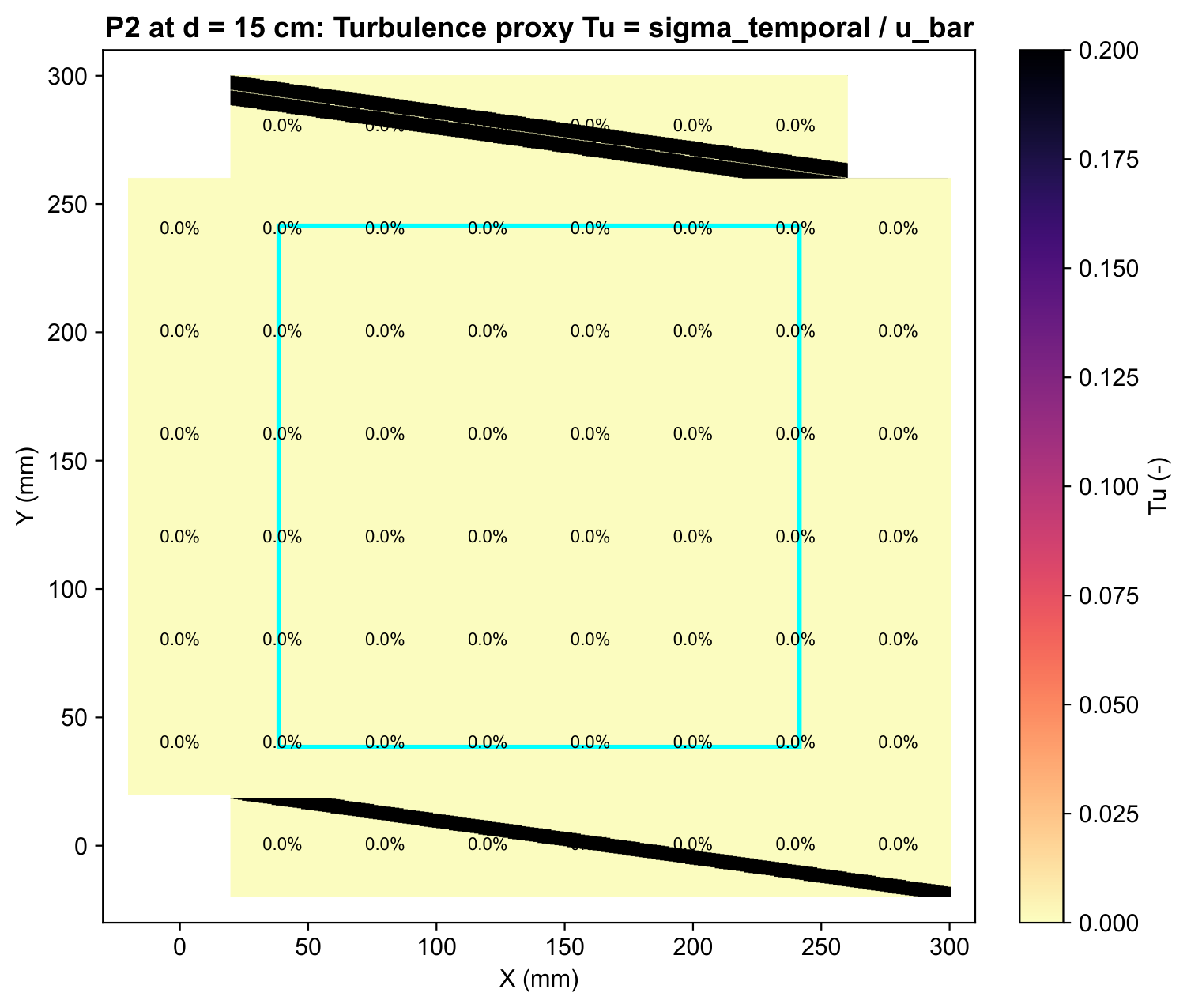
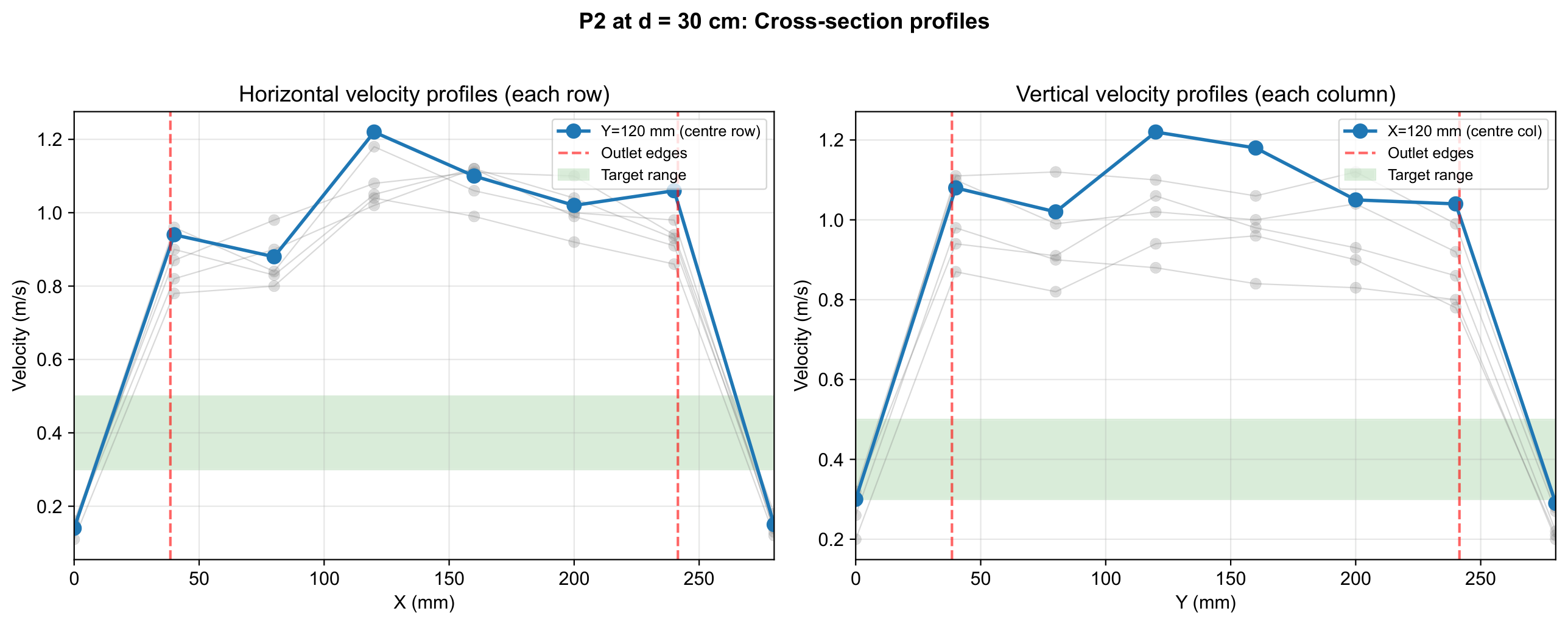
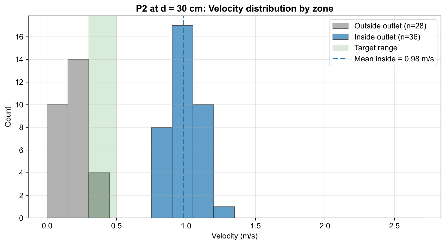
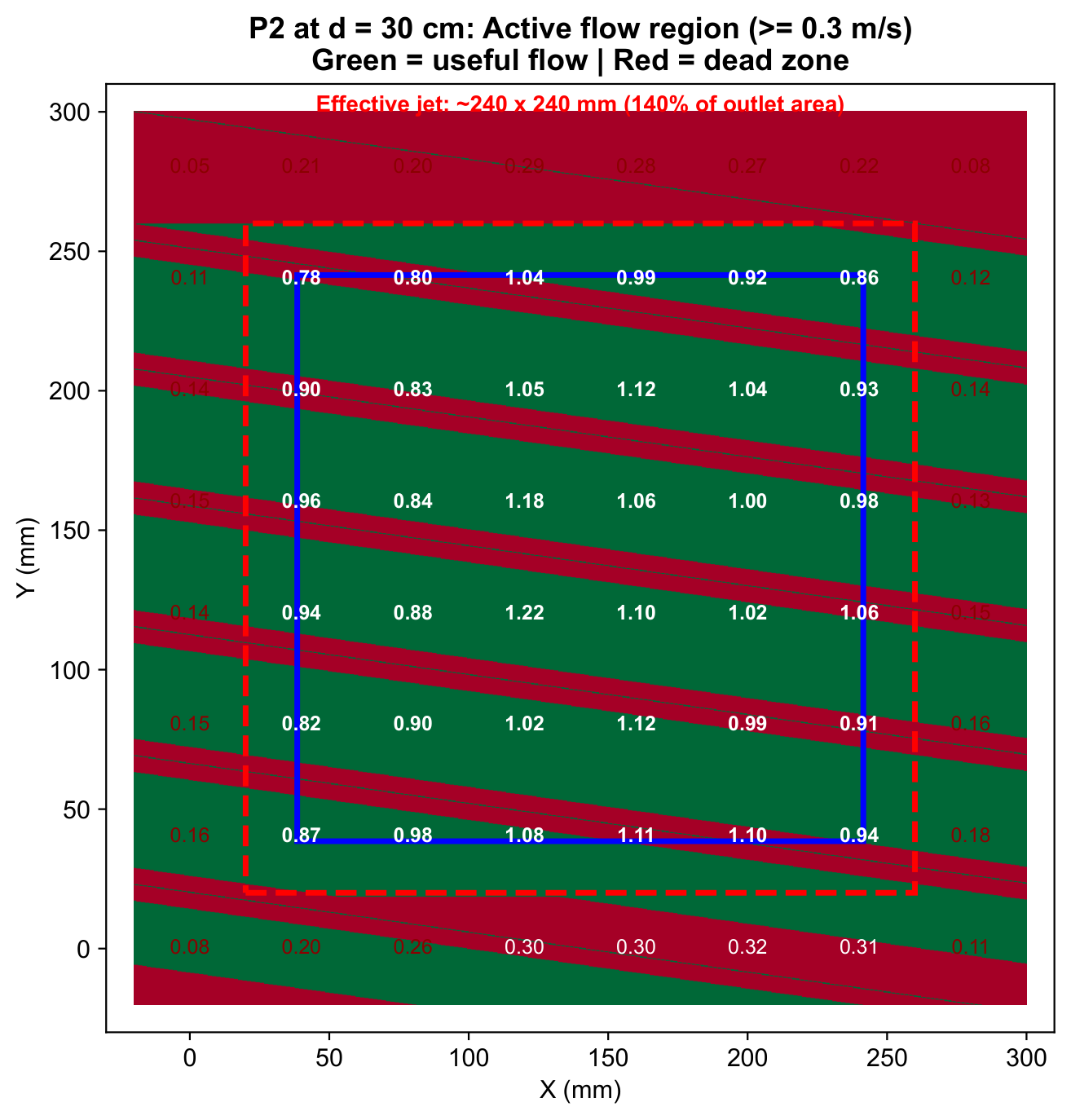
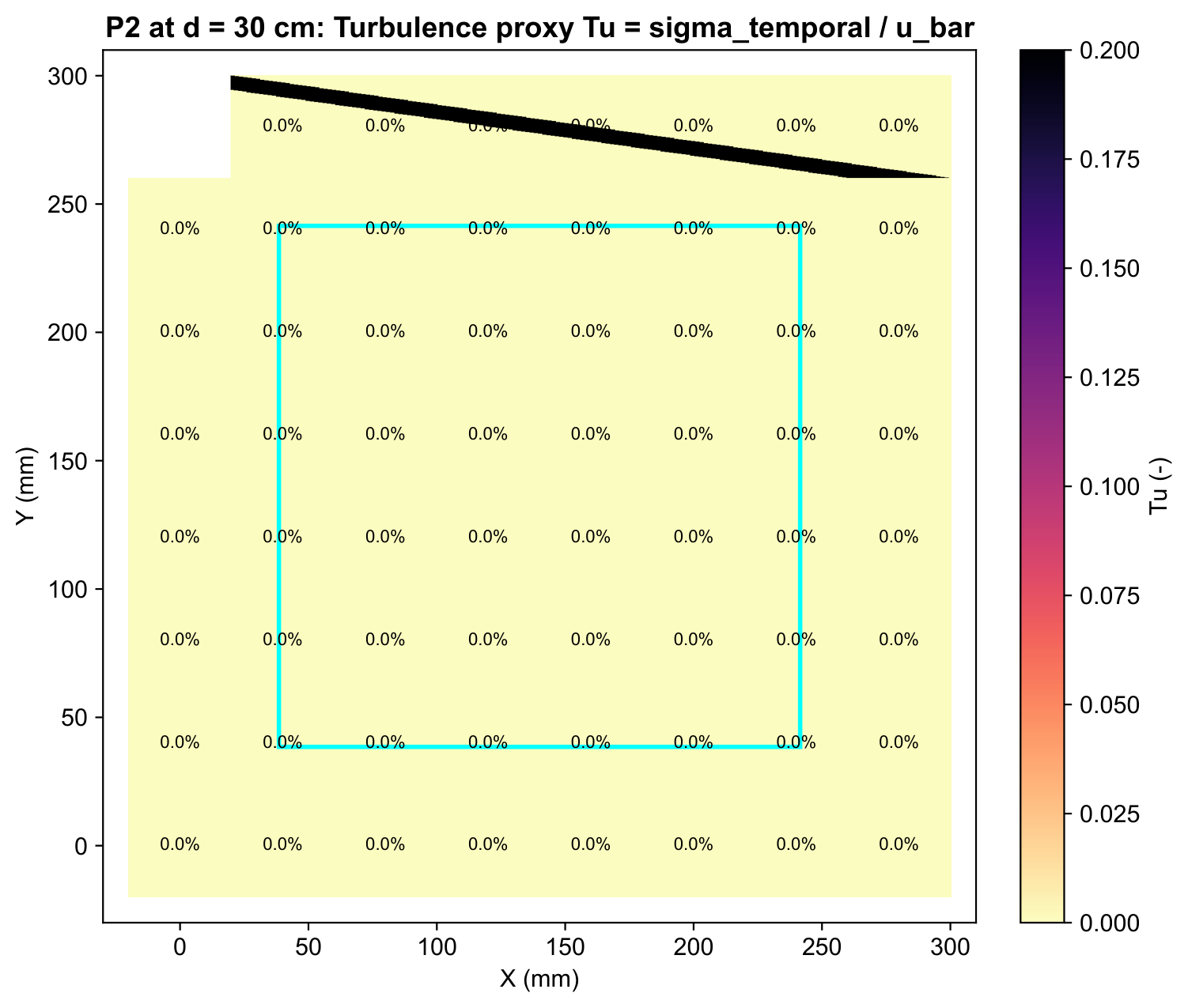
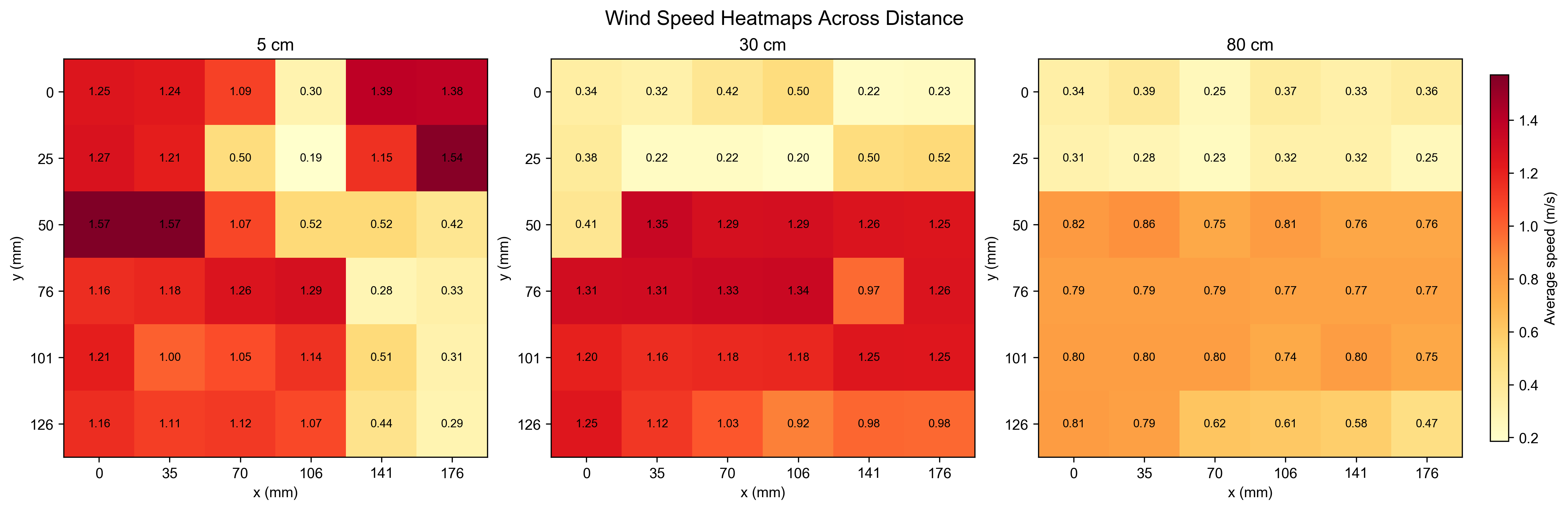
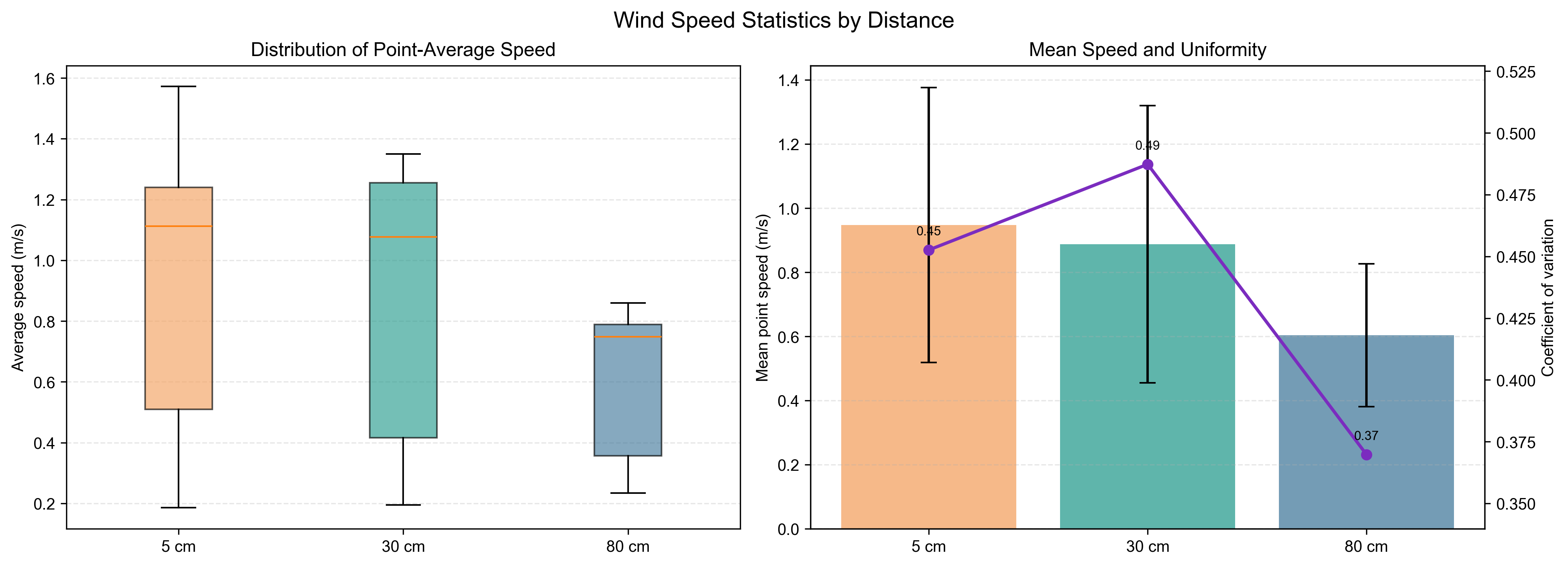
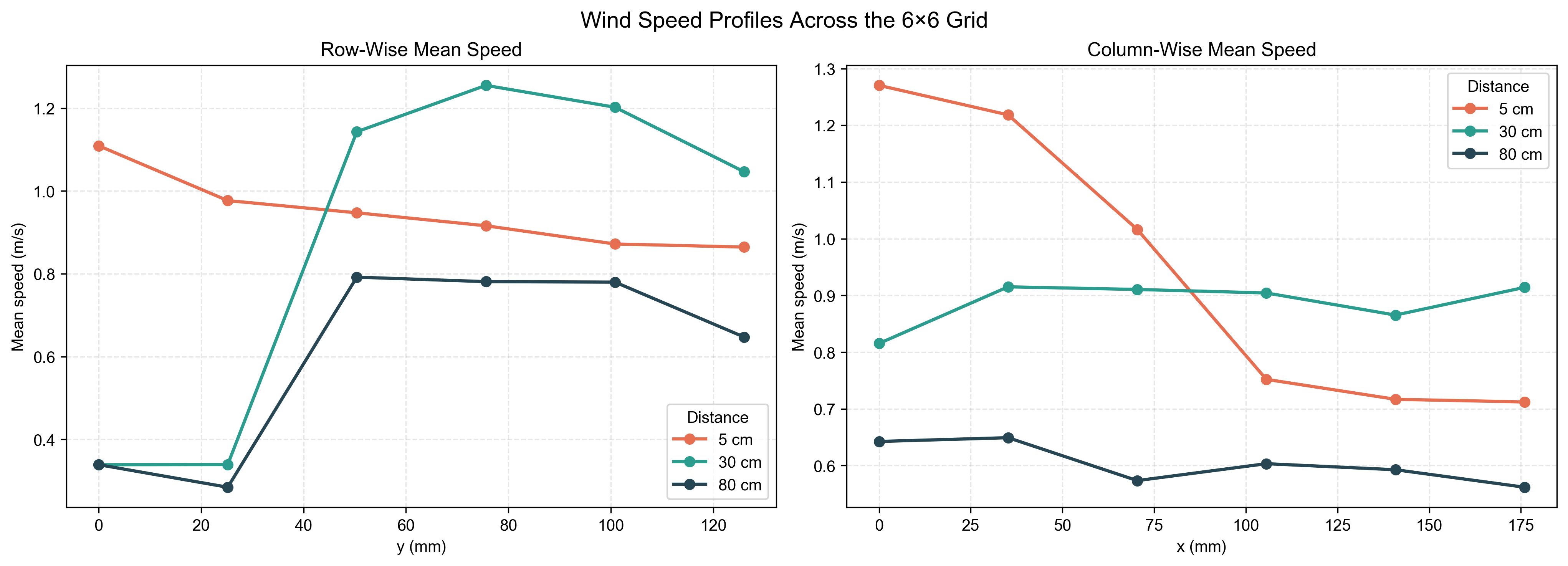
P1 Test Results
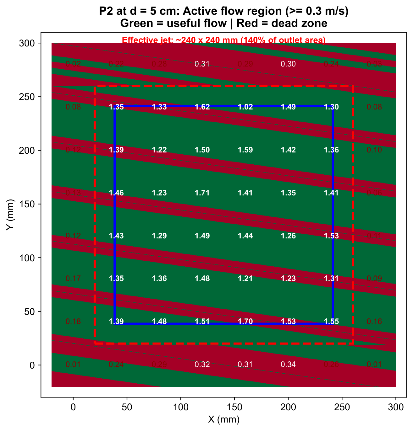
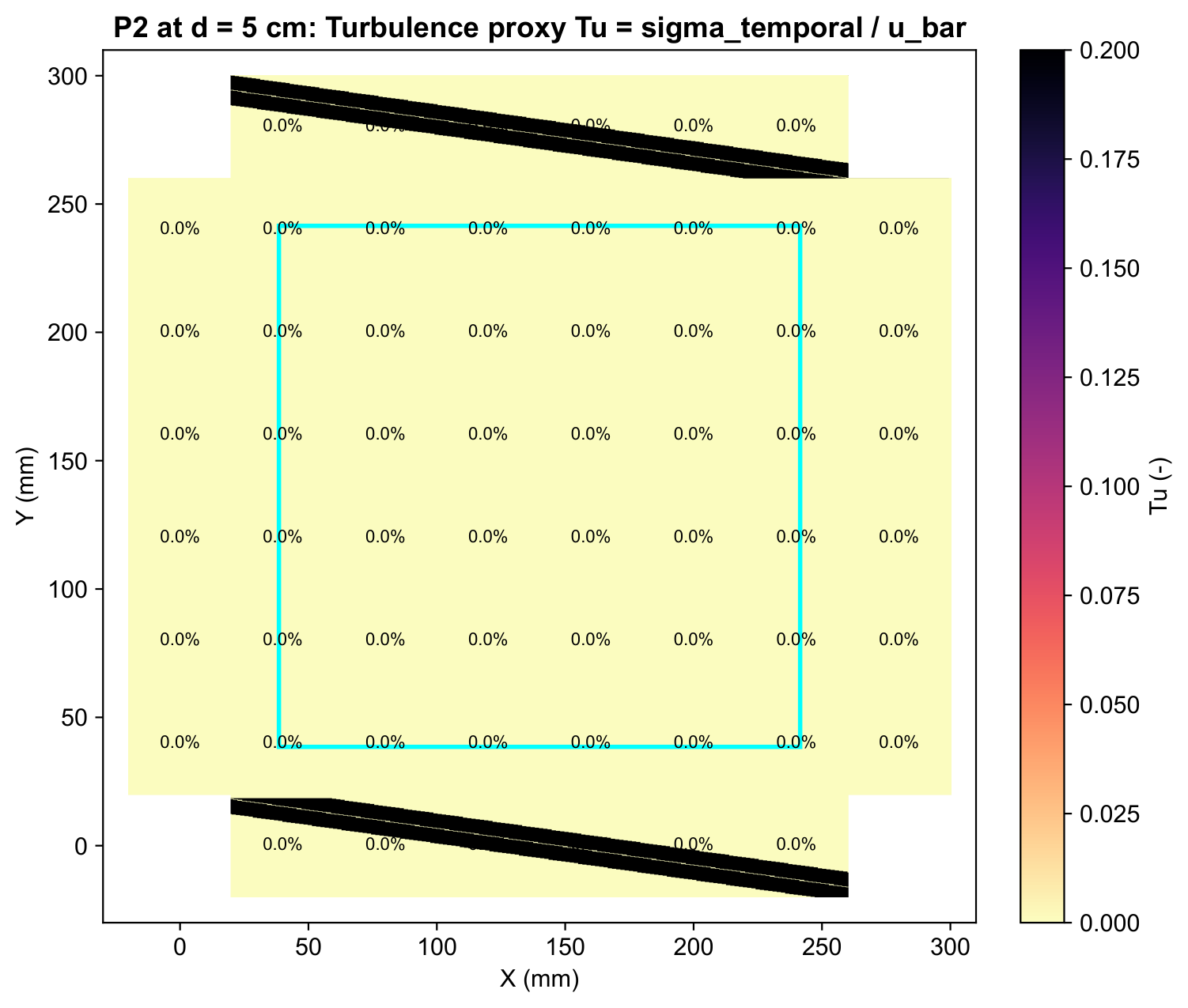
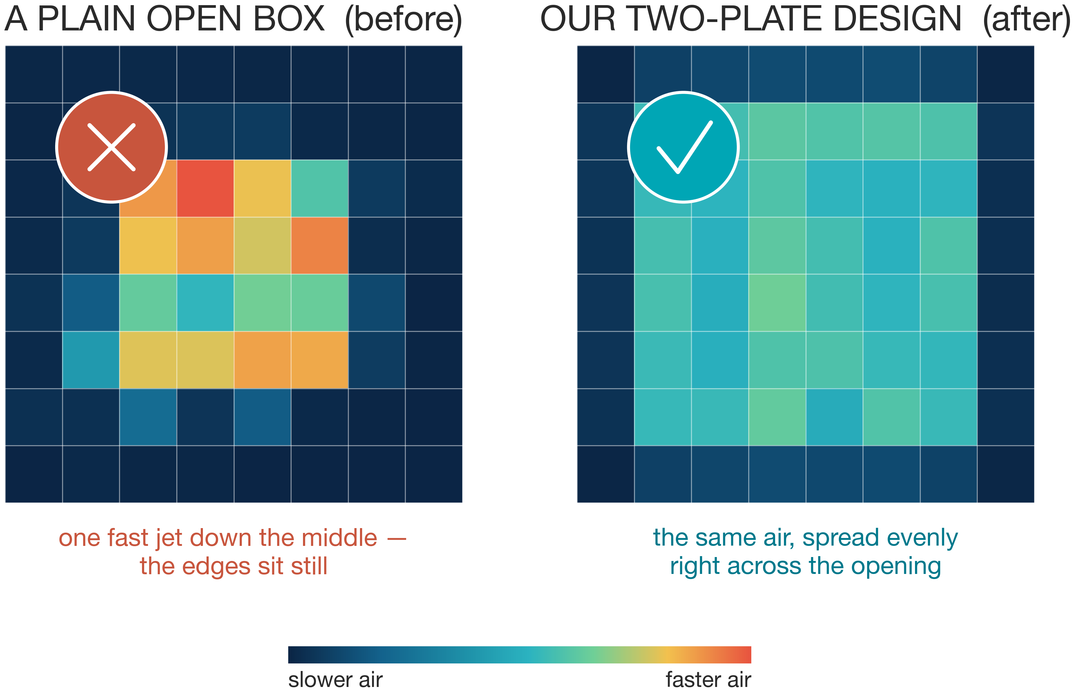
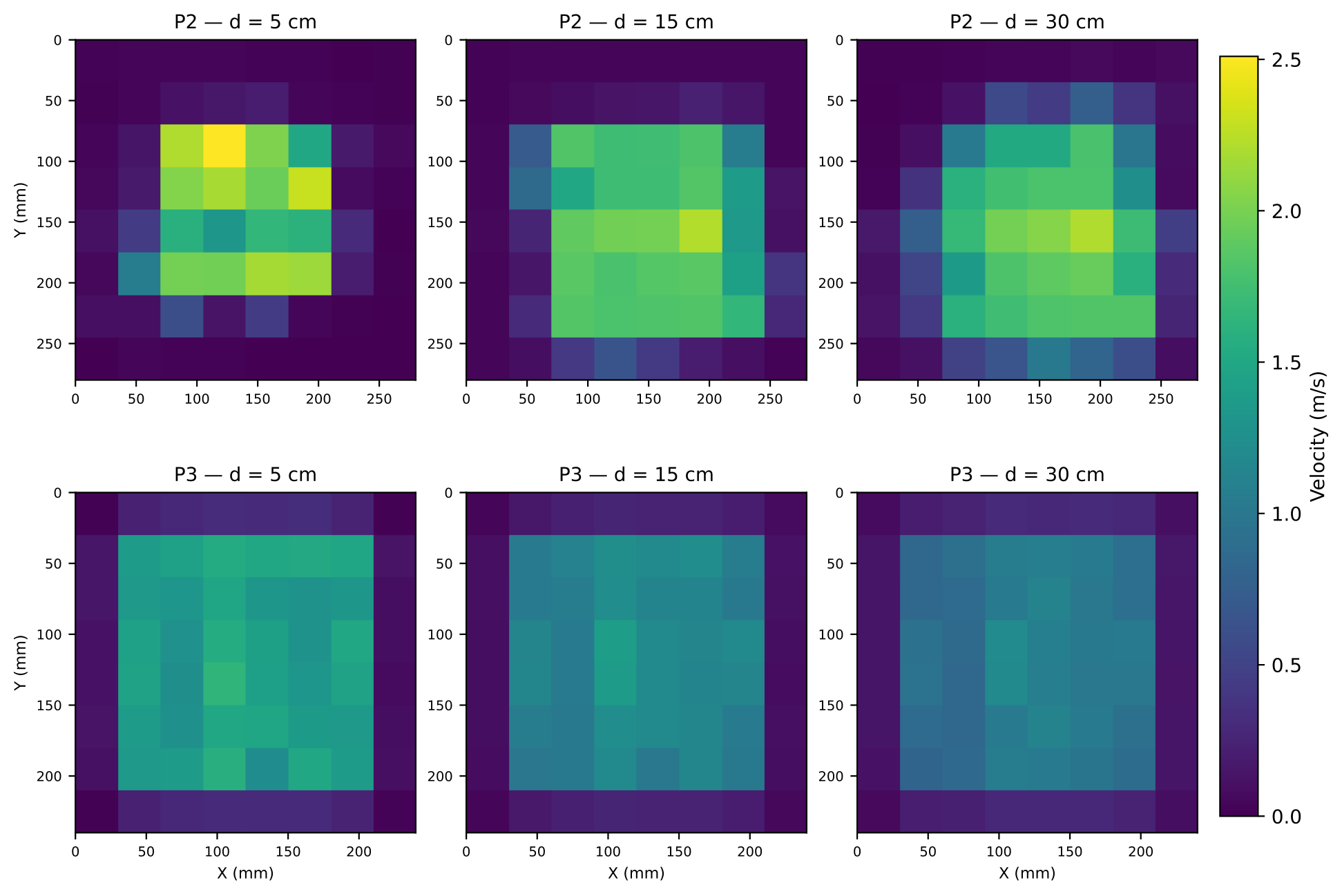
Velocity heatmaps
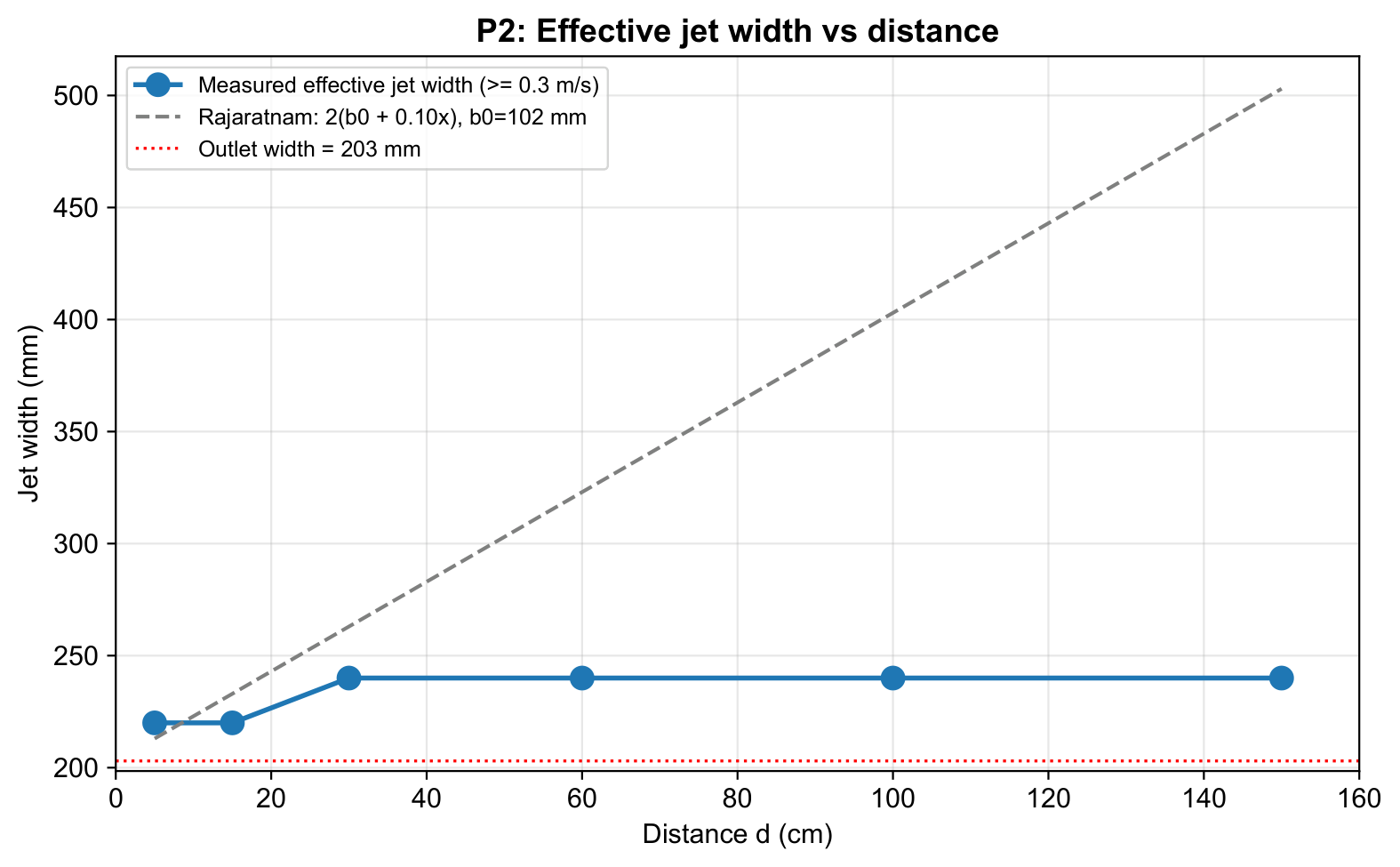
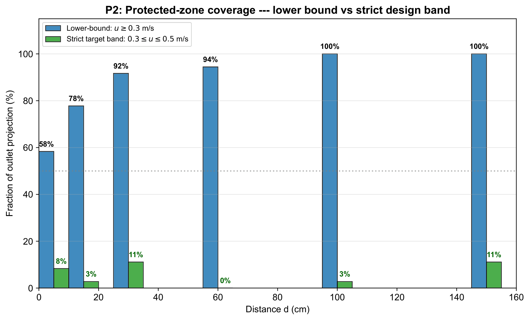
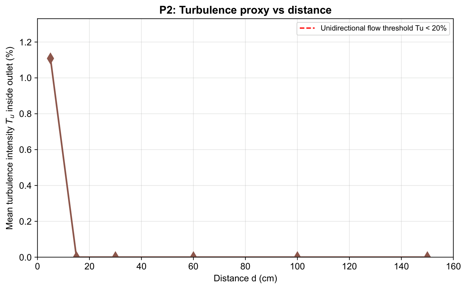
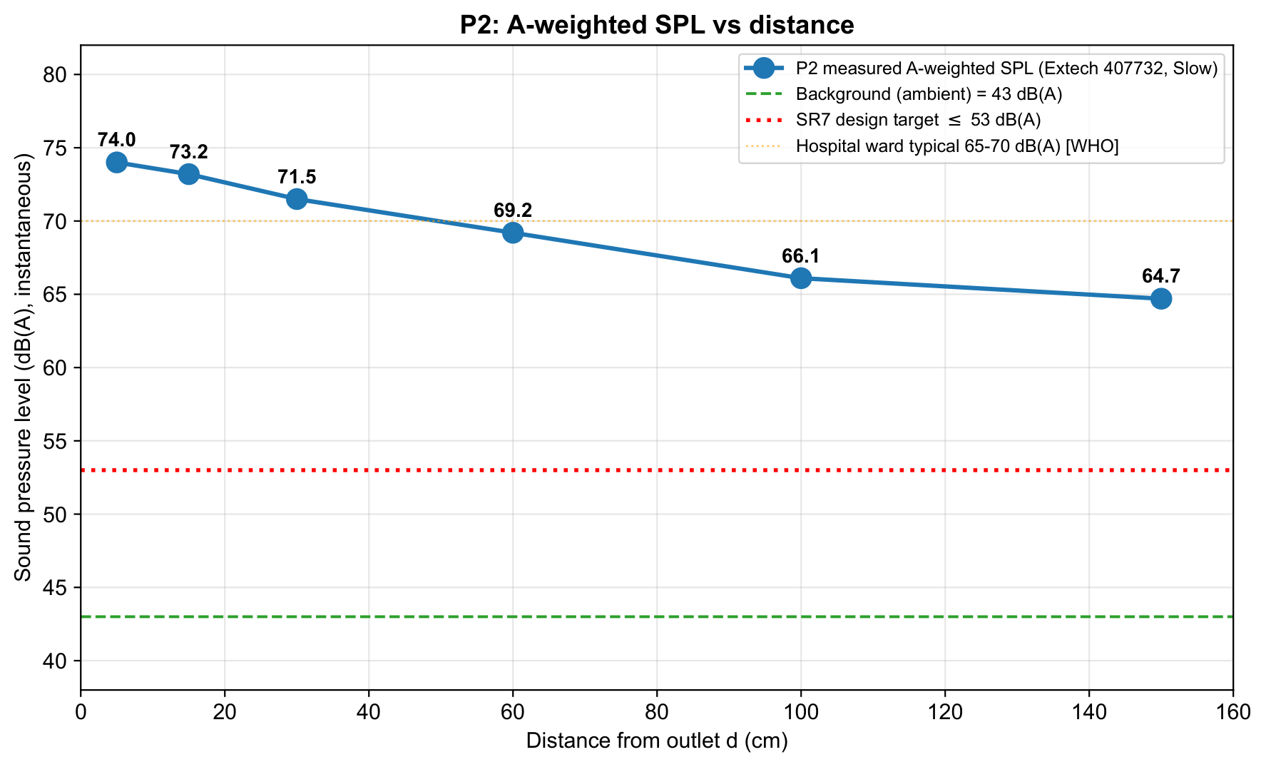
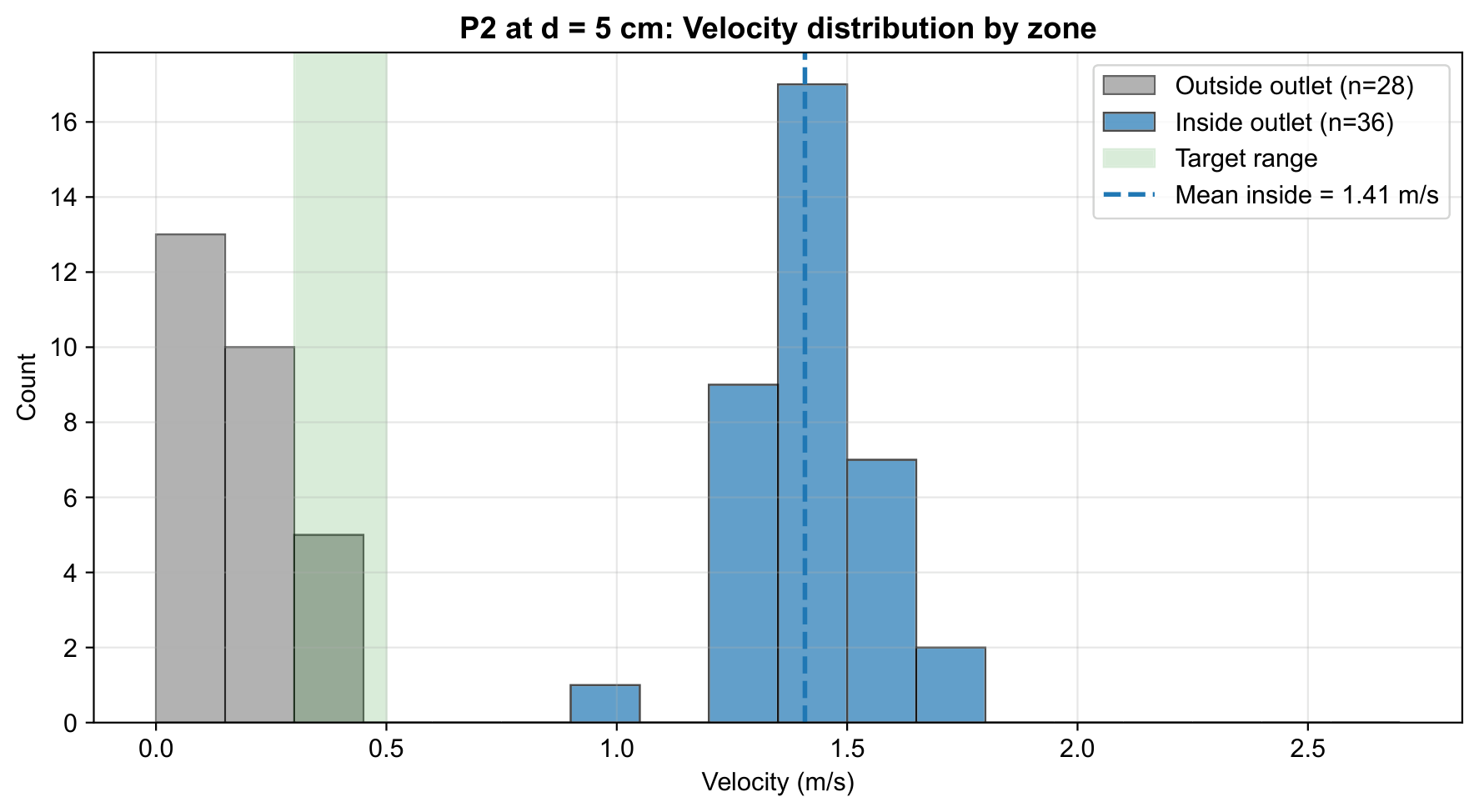
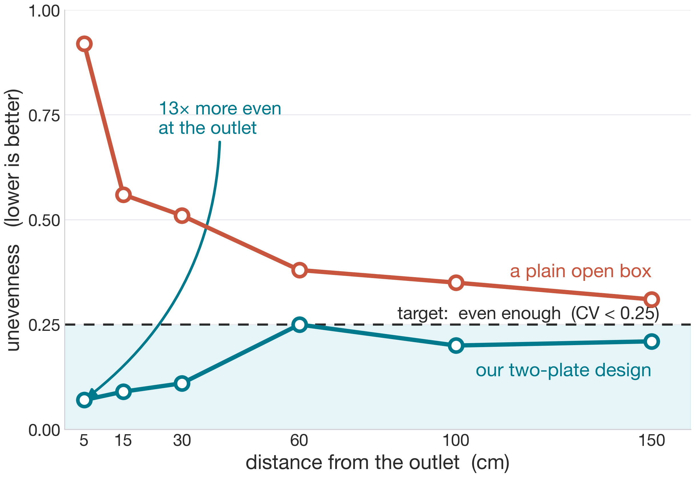
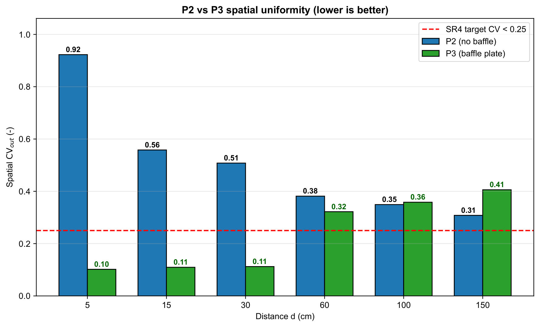
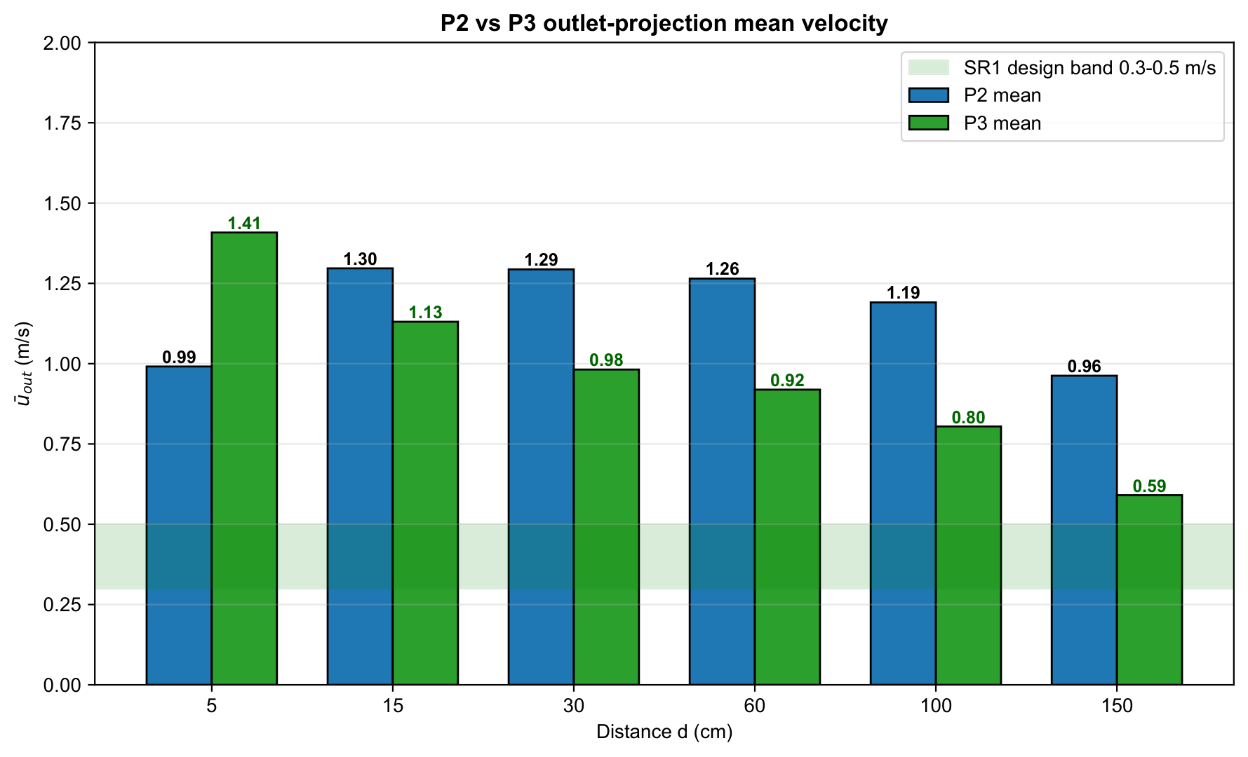
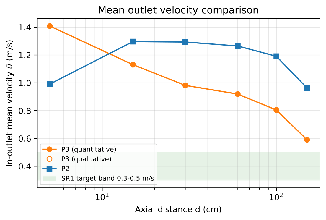
Wind speed statistics
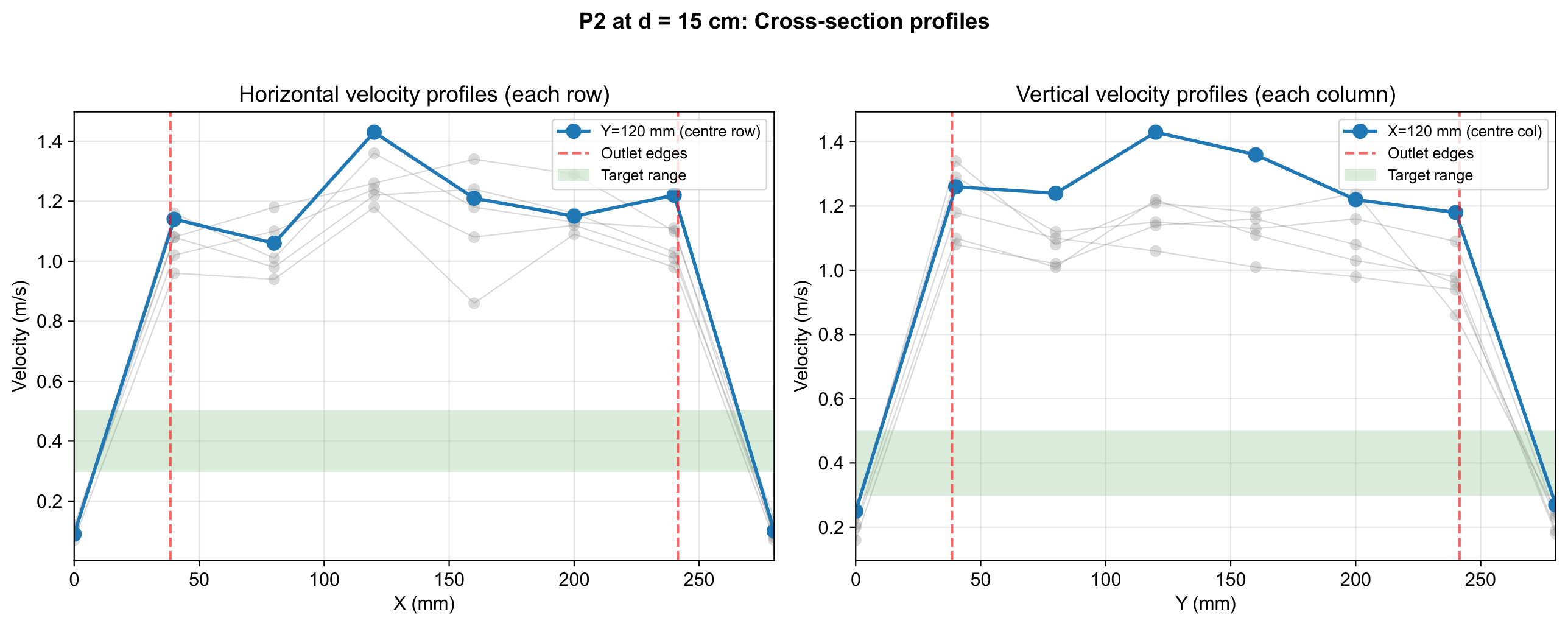
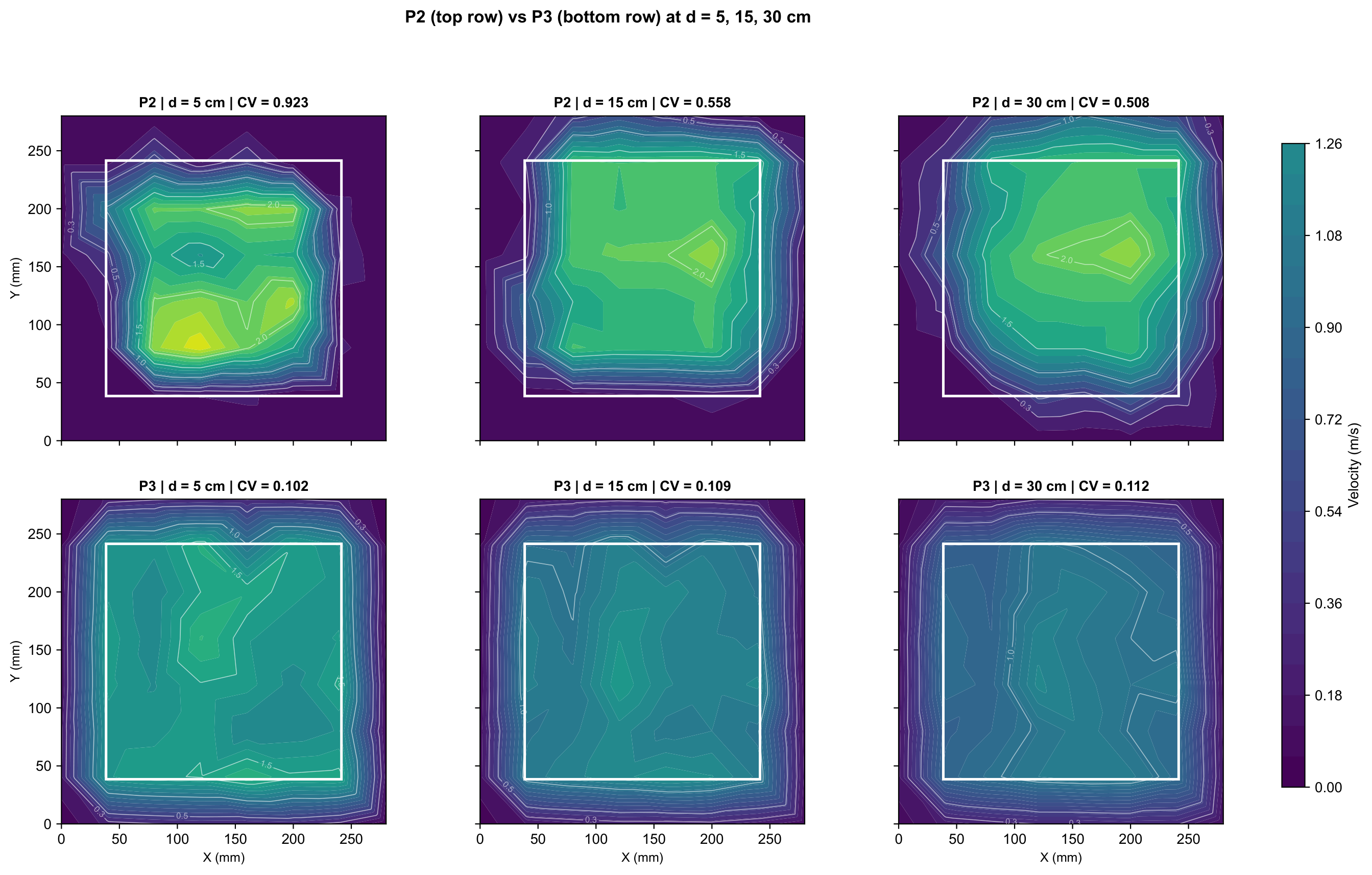
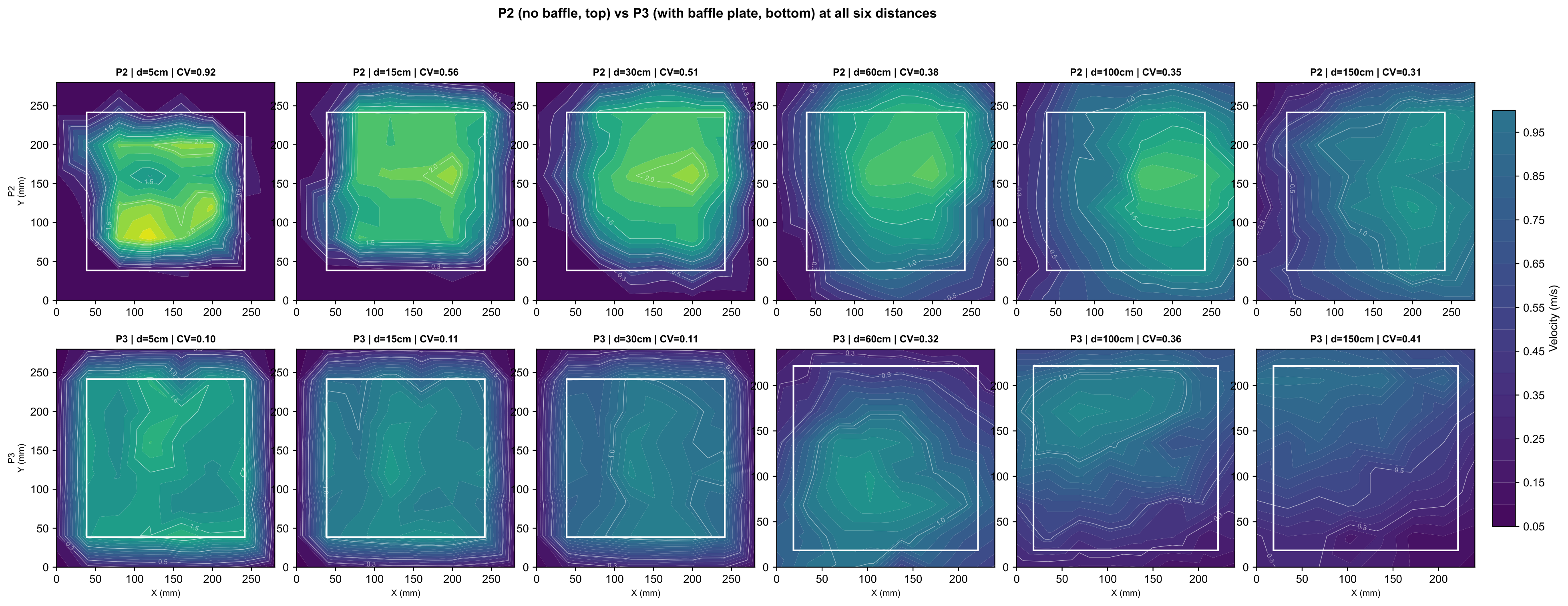
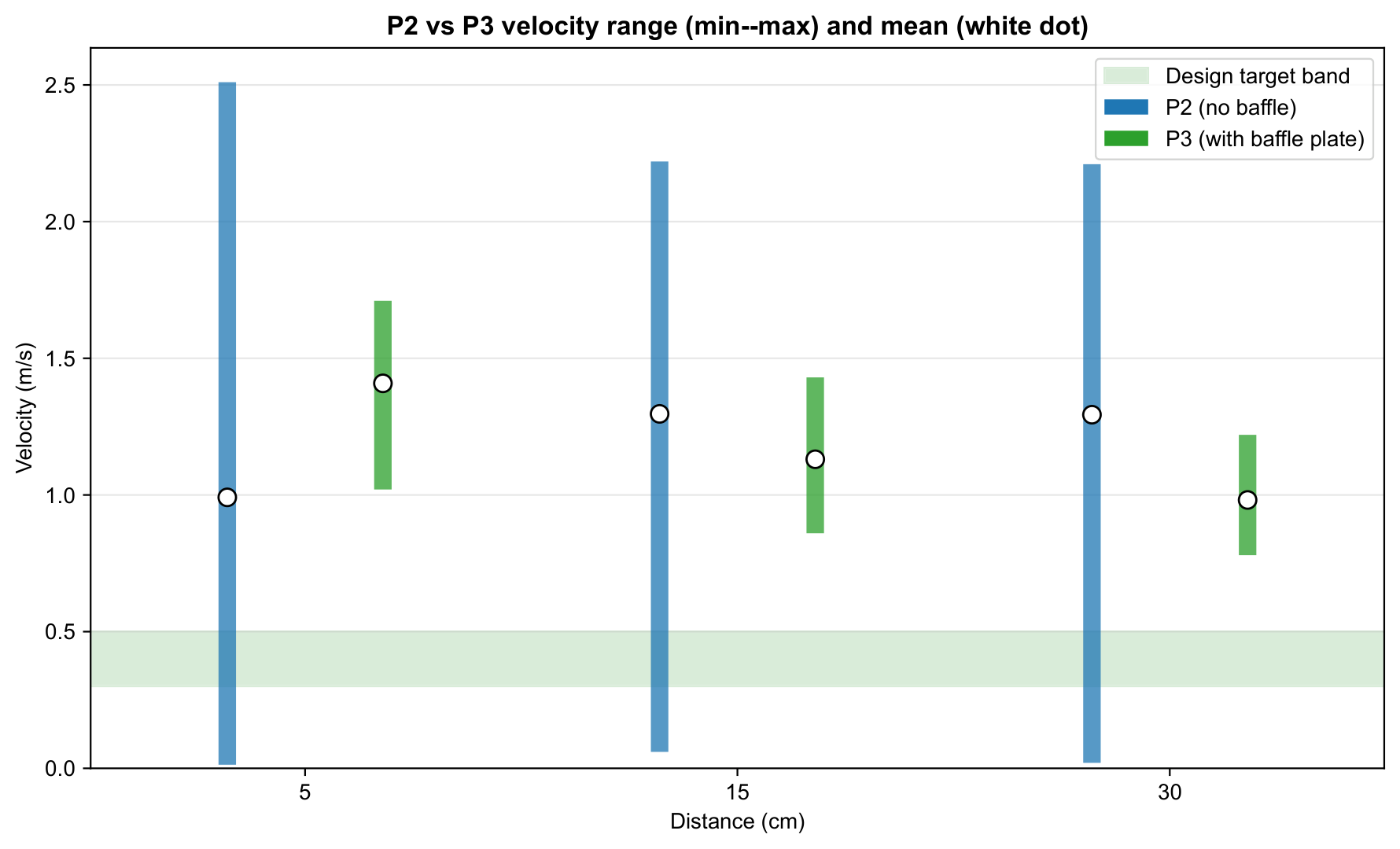
Velocity profiles